


CIRCUIT DESCRIPTION
4-10
November 1999
Part No. 001-7780-500
caused by high input levels from the internal or
external microphone. The bias voltage to this stage
and also to IC201A is produced by voltage divider
R208/R207.
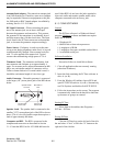
4.8.3 LOW-PASS FILTER (IC205A/B)
IC205A and IC205B form a low-pass splatter
filter which attenuates frequencies above approxi-
mately 3 kHz. This prevents adjacent channel interfer-
ence caused by the harmonic frequencies which result
from amplitude limiting.
The output signal from this filter is applied to
IC209 which contains four logic-controlled potentio-
meters. The transmit audio signal is applied to potenti-
ometer3onpin20andfedoutonpin19whichisthe
wiper of that potentiometer. The potentiometers in this
device are adjusted by the control logic via the serial
data bus (MSCK/MSO). The transmit audio/DTMF
level is set when the transceiver is aligned.
The transmit audio/DTMF signal is then fed to
IC201 where it is combined with the transmit data/
SMARTNET data signal if applicable. The output
signal on pin 4 of IC201 is then fed to the VCO in the
RFunitandalsotopins7and8ofIC209.Thesignal
fed to the RF unit (MOD) modulates the VCO, and the
signal fed to IC209 is level adjusted and fed out on pin
6 and applied to the RF unit where it modulates the
TCXO. The potentiometer is set by the logic during
alignment, and is used to balance the VCO and TCXO
modulation signals.
4.9 SMARTNET DATA PROCESSING
Both the transmit and receive SMARTNET/
SmartZone data signals are applied to a filter formed
by IC112A/B and IC113B. Switching of these signals
is provided by gate IC110 which is controlled by the
SN_TR signal from pin 95 of the microprocessor.
When this signal is high, the transmit data signal on
pin6isselectedisroutedtothefilter,andwhenitis
low the receive data signal on pin 7 is routed to the
filter.
IC112B, IC112A, and IC113B form a 1800 Hz
low-pass filter which attenuates unwanted frequencies
above the SMARTNET/SmartZone data band. The
output of this filter on U113B, pin 7 is then fed to
IC114A/B which provide DC restoration when data is
being received. The signal is also fed to gate IC210 in
the transmit data circuit to be transmitted when
applicable.
The DC restoration circuit formed by IC114A/B
and IC113A is similar to the receive data circuit
described in Section 4.7.1. It converts the data signal
from AC floating at half supply to DC levels of 0 and
5 volts that can be detected by the microprocessor.
Diodes D104 and D105 charge and discharge C158
andC157toestablishaDCreferenceonpin2of
comparator IC113A that is the average of the positive
and negative going alternations. Q106 turns on in the
transmit mode which grounds pin 2 and disables this
circuit.
In the transmit mode, gate IC210 selects either
the SMARTNET data signal or the Call Guard data
signal. It is controlled by the same SN_TR signal that
controls IC110. The output signal on pin 1 is then
applied to potentiometer 1 in IC209. Refer to Section
4.7.2 for more information on this circuit.