ALIGNMENT PROCEDURE AND PERFORMANCE TESTS
6-5
November 1999
Part No. 001-7780-500
3. Follow the instructions on the screen and adjust for
the best demodulated square wave with minimum
tilt and overshoot.
6.4 AUDIO DEVIATION
1. If manually selecting each test, click the “Tune”
button in the “Audio Deviation” box. Otherwise,
this function is selected automatically when the
“Complete Tune” button is clicked.
2. Inject a 1 kHz signal at the level indicated on the
screen into the Mic Audio jack of the RPI (see
Section 6.1.2).
3. Monitor the transmit modulation signal with a
communication monitor and follow the instructions
on the screen to adjust the wideband, narrow band,
and NPSPAC (see Section 1.2.5) deviation.
6.5 DATA DEVIATION
1. If manually selecting each test, click the “Tune”
button in the “Data Deviation” box. Otherwise, this
function is selected automatically when the
“Complete Tune” button is clicked.
2. Monitor the transmit modulation signal with a
communication monitor and follow the instructions
on the screen to adjust the wideband, narrow band,
and SMARTNET/SmartZone control channel
data deviation.
6.6 SQUELCH ADJUST
The input level to the noise squelch circuit is set
by R13 on the IF board, and the squelch threshold
level is set by the PCTune software. The factory
setting of R13 should not need to be changed, so step 3
which follows can normally be skipped. Proceed as
follows to set the squelch:
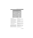
1. If manually selecting each test, click the “Tune”
button in the “Squelch” box. Otherwise, this func-
tion is selected automatically when the “Complete
Tune” button is clicked.
2. Connect an RF signal generator to the antenna jack
using a 6 dB or greater pad. Set the generator for the
channel frequency and modulation indicated on the
screen.
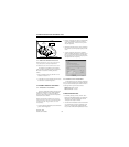
3. If R13 must be adjusted (see preceding), remove the
transceiver cover and connect power as described in
Section 6.1.6. Temporarily set the squelch for “50”
on the “Squelch” screen and adjust R13 (see Figure
6-3) so that the squelch just opens (audio is heard) at
8-9 dB SINAD.
4. Readjust the squelch level as indicated on the screen
so that the squelch opens and closes between the
indicated SINAD levels.
6.7 RSSI ADJUST
NOTE: Improperly setting the RSSI levels can result in
degraded SmartZone roaming operation. Therefore,
do not change the default settings unless you are
familiar with how roaming will be affected.
The function which adjusts the RSSI levels is
available only by clicking the “Tune” button in the
“RSSI” box. It is not displayed in the Complete Tune
mode for the reason just described. The default values
that are programmed by clicking the “Program
Defaults” button (see Section 6.1.5) should not be
changed unless you are familiar with how these levels
control site switching in a SmartZone system.


