


ALIGNMENT PROCEDURE AND PERFORMANCE TESTS
6-6
November 1999
Part No. 001-7780-500
PERFORMANCE TESTS
6.8 RECEIVER PERFORMANCE TESTS
6.8.1 PRELIMINARY SETUP
This transceiver does not have a special test mode
that can be selected to perform testing. Therefore,
temporary conventional channels are programmed to
perform this function. Program channels near the low,
middle, and high ends of the band (wideband, narrow
band or both) and with and without Call Guard
(CTCSS/DCS) squelch as applicable. In addition, to
check high and low power and talk-around operation,
program High/Low Power and Repeater Talk-Around
option switches. Proceed as follows to check receiver
operation:
1. Select the channel near the center of the band
(around 860 MHz).
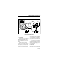
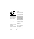
2. Connect the signal generator to theantenna jack (see
Section 6.1.2 for more information). Set the output
to the channel frequency, modulated with 1 kHz at 3
kHz (wideband channels) or 1.5 kHz deviation
(narrow band channels).
6.8.2 SINAD SENSITIVITY
NOTE: The audio output level of the accessory con-
nector is at a lower level than at the internal speaker.
In addition, the internal speaker automatically mutes
when a load of approximately 1k ohm or less is con-
nected to this output.
1. Connect a SINAD meter to the speaker output of the
RPI (see Section 6.1.2).
2. Decrease the signal generator output to obtain a 12
dB reading on the SINAD meter. The signal gener-
ator output should be 0.35 µV maximum. If
required, temporarily readjust squelch for “0” as
described in Section 6.6. (after clicking “Read Tune
Settings” to note the current setting).
3. Check both wide and narrow band channels if appli-
cable, and also check the channels on each end of
the band. Reset the squelch to the previous level if it
was changed.
6.8.3 SQUELCH SENSITIVITY
With the test setup used for the preceding test,
slowly increase the signal generator output until the
squelch just opens (audio is enabled). Then decrease
the signal generator output until it just closes. The
squelch should open after 12 dB SINAD and close
before 6 dB SINAD.
6.8.4 AUDIO POWER AND DISTORTION
CAUTION
Grounding either speaker terminal may damage the
audio amplifier. Therefore, make sure that any meter
connected across the speaker has floating inputs.
To measure audio output power, the actual level
across the speaker must be measured because full
output power is not available at the accessory
connector. If a load of approximately 1k ohm or less is
connected to the speaker output of the accessory
connector, it must be disconnected to enable the
internal speaker. Proceed as follows:
1. Remove the transceiver cover and connect power as
described in Section 6.1.6. Carefully turn the front
cover over to access the speaker.
2. Connect an AC voltmeter and distortion meter
across the speaker (make sure they have floating
inputs). Alternatively, 100 µF, non-polarized capac-
itors can be used in series with the leads.
3. Set the signal generator output for –60 dBm (220
µV). Minimum audio power should be 0.5 watt
across the 16-ohm speaker (2.8 V rms). Distortion
should be less than 5% at 0.5 watt.
6.8.5 RECEIVER CURRENT DRAIN
Maximum transceiver current with 0.5-watt audio
output is 300 mA. With the receiver squelched, it
should be 92 mA maximum.