


GENERAL INFORMATION
1-6
November 1999
Part No. 001-7780-500
1.11 ACCESSING PC BOARDS
1.11.1 INTRODUCTION
The RF unit is located under the back cover and
the logic unit is located under the front cover. These
boards connect together using a 30-pin connector on
the bottom side. Since both boards have numerous
parts on the bottom (hidden) side, the board may need
to be removed to replace components. To operate the
transceiver with the RF unit removed, a special exten-
sion test cable is required.
Also inside the transceiver are display and
keypad boards. These boards are mounted to the inside
of the front cover. Proceed as follows to remove the
RF and logic unit board from the transceiver.
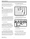
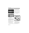
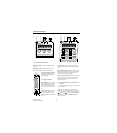
1.11.2 REMOVING TRANSCEIVER CASE
To access the internal parts in the transceiver, the
plastic case must first be removed. Proceed as follows:
1. If you have not already done so, remove the battery
by pressing the release button upward and then
sliding it off the transceiver. If the belt clip is
mounted on the back, it must also be removed.
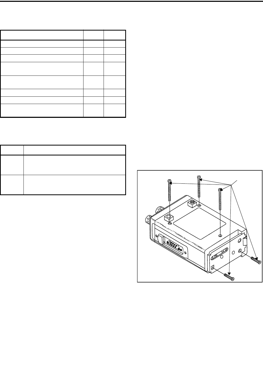
2. Remove the three screws in the back and two in the
bottom end that are indicated in Figure 1-1. Slide the
case off.
3. Removing the two screws in the end also allows the
front panel to be removed. Simply lift it outward if
desired. If you do not want to remove the front
panel, temporarily replace one of the end screws.
CAUTION
Excessive flexing of the ribbon cables may result in
broken traces.
Figure 1-1 Removing Case Screws
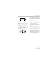
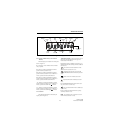
1.11.3 UNPLUGGING FLEX CABLES
The flex cable to the front panel and also the
accessory jack and PTT switch flex cables to the logic
board are inserted into a locking-type connector. To
release the cable so that it can be removed from the
connector, the locking tangs must be pulled out as
shown in the following illustration.
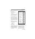
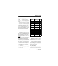
Table 1-2 Material Classification
Typical Hazard Group Class
Acetylene A I
Hydrogen B I
Ethylene, ethyl ether, cyclopropane C I
Gasoline, naphtha, butane, propane,
alcohol, acetone, benzol, natural gas
DI
Metal dust including aluminum, mag-
nesium, and their alloys
EII
Carbon black, coal, or coke dust F II
Flour, starch, or grain dusts G II
Ignitable fibers/flyings such as rayon
or cotton
-III
Table 1-3 Area Classification
Division Area
1 An area where there is or could be an explosive
atmosphere most of the time in normal opera-
tion
2 An area where an explosive atmosphere exists
only as a result of a fault (something going
wrong)
REMOVE
THESE
SCREWS