CIRCUIT DESCRIPTION
4-9
November 1999
Part No. 001-7780-500
cut-off frequency is approximately 190 Hz. Q103
lowers the cut-off frequency of the filter by switching
additional capacitance into the filter.
From the filter the data signal is applied to a DC
restoration circuit formed by IC107B and IC107A.
This circuit converts the data signal from AC floating
at half supply to a digital signal at 0- and 5-volt levels
that can be read by the microprocessor. IC107B is a
standard noninverting amplifier with a gain of approx-
imately 5.6 set by R139 and R140 (R140 is AC
grounded by C129). Diodes D101 and D102 charge
and discharge C129 to establish a DC reference on
pins 2 and 6 of IC107 that is the average of the posi-
tive and negative going alternations of the data signal.
The amplified data signal is applied to pin 3 of
IC107A. When this level rises above the reference
level on pin 2, the output on pin 1 goes high (5 volts).
Conversely, when the data signal falls below the refer-
ence level, the output goes low (0 volts). In the
transmit mode, Q104 is turned on which effectively
grounds pin 3 of IC107A and forces the output on
pin 1 low.
4.7.2 TRANSMIT DATA FILTER (IC206B/
IC206A)
Thetransmitdatasignalisproducedbythe
TXDATA and TXPREC outputs of the micropro-
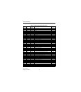
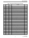
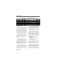
cessor (pins 27 and 34, see Table 4-1). A pseudo sine
wave is produced by the four voltage levels that can be
produced by these outputs. This signal is fed to a
transmit data filter formed by IC206B and IC206A.
This filter is the same as receive data filter IC102B
and IC102A described in the preceding section. This
filter attenuates harmonics present in the waveform
produced by the microprocessor.
The output and input of the data filter is fed to
gate IC203. This gate is used to bypass the transmit
data circuit during alignment so that a wide range of
harmonic frequencies are passed for use in setting
modulation balance. The control signal to this gate is
the TEST signal from pin 35 of the microprocessor.
This signal is low when the transmit data filter is
bypassed.
Thesignalisthenroutedtopin7orgateIC210
which selects either it or the SMARTNET data signal
from IC113B. The data output signal on IC210, pin 1
is then applied to pin 24 of IC209 which is the input to
one of the digitally controlled potentiometers in that
device. The data modulation level is set during align-
ment and controlled by the logic. The output on pins
22 and 23 is then fed to IC201 where it is combined
with the transmit audio signal (see Section 4.8.3).
4.8 TRANSMIT AUDIO PROCESSING
4.8.1 GATE (IC204), HIGH-PASS FILTER
(IC202)
The microphone audio signal is applied to pin 2
of one of the gates in IC204. This signal may come
from the internal microphone or an external micro-
phone connected to pin 8 of the accessory connector.
This gate is controlled by the MMUTE signal from pin
33 or the microprocessor. When this signal is low, the
microphone audio signal is muted.
The transmit DTMF tone is applied to pin 6 of
IC204 which is the input of the other gate in that
device. This gate is controlled by the DTMFMT signal
from pin 82 of the microprocessor, and when that
signal is low, the DTMF tone is muted.
The transmit audio and DTMF signals are then
combined and applied to pin 3 of compandor IC208.
When companding is enabled by a low input on the PT
input of IC208, this stage provides 2:1 compression of
the audio signal. This compression and then re-expan-
sion when it is received reduces the amount of noise
present in the audio signal. When the PT input of
IC208 is high, companding is disabled and the signal
is fed through IC208 without compression. NOTE:
Companding is not currently used with this radio.
The transmit audio/DTMF signal is fed out of
IC208 on pin 2 and applied to a high-pass filter formed
by IC202A. This filter has a –3 dB cutoff frequency of
approximately 300 Hz to attenuate frequencies that
could cause interference with the Call Guard signals.*
4.8.2 LIMITER (IC202B)
Pre-emphasis of the DTMF tone or microphone
audio signals is provided by C205/ R211. IC202B is
an amplifier functioning as a limiter (limiting occurs
when it saturates). Limiting prevents overmodulation


