28
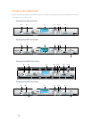
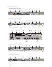
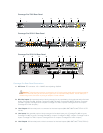
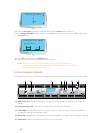
Link In and Link Out Ports6. : Two RJ-45 E-bus (expansion bus) connectors used to connect
multiple Converge Pro units together to create a site. You can connect up to twelve Converge Pro
840T/880/880T/880TA/8i/SR 1212/SR 1212A units, up to 16 Converge Pro TH20 units, or any combination
thereof, where the total number of microphone inputs does not exceed 96. Maximum cable length is 200 feet
using Category 5 unshielded twisted pair cable.
WARNING: Use the Link In and Link Out ports with Converge Pro Devices ONLY. Connecting
ANY other devices to the Link In and Link Out ports, including ClearOne XAP or PSR1212
products, or Power Over Ethernet (PoE) devices, will result in severe equipment damage.
RS-232 Serial Port7. : Female DB9 connector for connecting to a laptop, computer, or remote control serial
devices (such as AMX and Crestron controllers).
NOTE: Converge Console software cannot connect via the RS-232 port; use USB or Ethernet.
Control/Status A and B Ports8. : Two female DB25 connectors used for GPIO interactions between Converge
Pro devices and external control devices (such as wall switches and push-to-talk microphones). This enables
external devices and controller software to access the Converge Pro command set, including common
functions such as volume control, muting, room combining, and preset changes.
PC and LAN Ethernet Ports9. : Two RJ-45 10/100Mbps auto-sensing Ethernet ports. The LAN port connects
Converge Pro devices to a network. The PC port provides a pass-through network connection for use with a
standard (not crossover) patch cable. The LEDs adjacent to each port indicate connection status and packet
traffic activity.
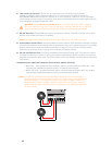
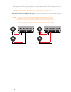
Speaker Posts (880T, 840T)/Amplifier Terminal Block (880TA, SR1212A)10. :
880T,840T--Twopost/bananaplugconnectorsusedtoconnectanexternalspeaker(4Ω–16Ω).•
Internal power amplifiers eliminate the need for an external power amplifier.
880TA,SR1212A--8speakerterminalsusedtoconnectanexternalspeaker(8Ω).Four,35Watt•
internal power amplifiers eliminate the need for an external power amplifier.
NOTE: To reduce risk of electrical shock and damage to equipment, never connect wiring or
external equipment while the amplifier is power is on. Class 2 wiring is required. Maintain
the correct polarity (+/-) on output connectors. (For example: Channel 1 positive (+)
speaker lead connects to amplifier’s channel 1 positive terminal. Channel 1 negative (-)
speaker lead connects to amplifier’s channel 1 negative terminal. Repeat this procedure
for each channel.


