


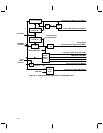
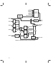
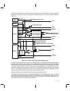
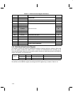
4–22
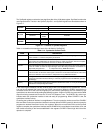
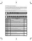
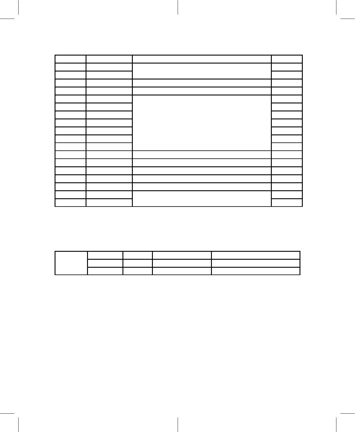
Table 4–17. Microcontroller Register Definitions
ADDR NAME CATEGORY R/W
00h WBDCtrl
Wide-band data
W
00h WBD
Wid
e-
b
an
d
d
a
t
a
R
01h FIFO FIFO A(B) microcontroller to DSP (DSP to microcontroller) W/(R)
02h MIntCtrl Interrupt/control status R/W
03h SynData0
Shi i f
W
04h SynData1
Shi i f
W
05h SynData2
Shi i f
W
06h SynData3
Synthesizer interface
W
07h SynCtrl0
y
W
08h SynCtrl1 W
09h SynCtrl2 W
0Ah MCClock Microcontroller clock speed W
0Bh RSSI A/D RSSI level R
0Ch BAT A/D Battery level monitor R
0Dh LCD D/A LCD contrast control W
0Eh MStatCtrl Miscellaneous status/control R/W
0Fh TXI Offset
Transmit dc offset compensation
W
10h TXQ Offset
T
ransm
it
d
c o
ff
se
t
compensa
ti
on
W
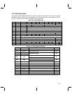
4.16 Wide-Band Data/Control Register
This register is used for two functions, depending on whether it is being read from or written to. When read
from, the register provides the latest 8 bits of received and demodulated data according to the
microcontroller register map to the microcontroller. When it is written to, the bits are placed into the WBDCtrl
register (see Table 4–16) as shown here:
7 6 5–3 2–0
WBDCtrl WBD_LCKD WBD_ON WBD_BW[2:0] Reserved
W W W
When the WBDCtrl register is read, bit 7 (MSB) is the last received data bit.
The definition of the WBDCtrl register, according to the DSP register map, is shown in Table 4–18.