1–5
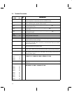
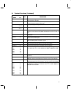
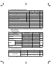
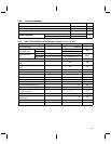
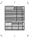
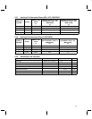
1.4 Terminal Functions (Continued)
TERMINAL
I/O
DESCRIPTION
NAME NO.
I/O
DESCRIPTION
DSPRW 69 I DSP read/write. A high on DSPRW enables a read operation and a low enables
a write operation to the DSP.
DSPSTRBL 68 I DSP strobe low. The DSPSTRL (active low) is used in conjunction with DSPCSL
to enable read/write operations to the DSP.
DV
DD
35, 45, 63,
75, 90
— Digital power supply. All supply terminals must be connected together.
DV
SS
34, 46, 65,
76, 91
— Digital ground. All supply terminals must be connected together.
DWBDINT 78 O DSP wide-band data interrupt (active low). The DWBDINT output goes low to
indicate that the wide-band data (WBD) demodulation circuits have traffic on
them.
FM 4 I Frequency modulation. FM terminal is connected to the output of the FM
discriminator.
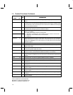
FMRXEN 95 O FM receive path enable. A high output from FMRXEN can be used to enable the
power for the receiver FM path.
IQRXEN 96 O In-phase and quadrature receive path enable. A high output on IQRXEN can be
used to enable the power for receiver I/Q path.
LCDCONTR 33 O Liquid-crystal display (LCD) contrast. This LCDCONTR control DAC can be
used to control the amount of drive to the liquid crystal display.
MCLKOUT 67 O Master clock out. MCLKOUT is a buffered version of MCLKIN.
MCA0 40
I Microcontroller 5-bit parallel address bus. MCA0 through MCA4 provide a 5-bit
b t dd th i t ll MCA4 i th MSB d MCA0 i th LSB
MCA1 41
pgp
bus to address the microcontroller. MCA4 is the MSB, and MCA0 is the LSB.
MCA2 42
MCA3 43
MCA4 44
MCCLK 62 O Microcontroller clock. MCCLK provides an adjustable frequency with 1.215 MHz
at powerup.
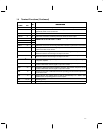
MCCSH 39 I Microcontroller interface chip-select. A high at MCCSH in conjunction with a low
at MCCSL allows the microcontroller to read from or write to the TCM4300.
MCCSL 38 I Microcontroller interface chip-select. A low at MCCSL in conjunction with a high
at the MCCSH allows the microcontroller to read from or write to the TCM4300.
MCD0 51
I/O/Z Microcontroller 8-bit parallel data bus. MCD0 through MCD7 provides an 8-bit
ll l d t b t d/ i d t t /f th i t ll MCD7 i th
MCD1 52
pgp
parallel data bus to send/receive data to/from the microcontroller. MCD7 is the
MSB and MCD0 is the LSB
MCD2 53
MSB
, an
d
MCD0
i
s
th
e
LSB
.
MCD3 54
MCD4 55
MCD5 56
MCD6 57
MCD7 58
†
Z = high impedance


