


1–6
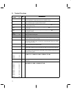
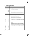
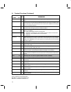
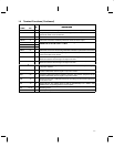
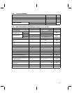
1.4 Terminal Functions (Continued)
TERMINAL
I/O
DESCRIPTION
NAME NO.
I/O
DESCRIPTION
MCDS 48 I Microcontroller data strobe. MCDS is configured by the signals present on MTS0 and
MTS1.
MCLKIN 64 I Master clock input. The MCLKIN frequency input requirement is 38.88 MHz ±100 ppm.
A crystal can be connected between MCLKIN and XTAL to provide an oscillator circuit.
As an alternative, XTAL can be left open and an external TTL/CMOS-level clock signal
can be connected to MCLKIN.
MCRW 47 I Microcontroller read/write. Microcontroller read/write operations are selected in
accordance with the signals present on MTS0 and MTS1.
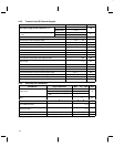
MTS0 36 I
Microcontroller type select configuration-control inputs. The interface is controlled by
MTS (1:0) as follows:
00 – Intel microcontroller interface characteristics
MTS1 37 I
10 – Mitsubishi and Motorola microcontroller 16-bit bus interface characteristics
01 – Motorola microcontroller 8-bit bus characteristics
11 – Reserved
MWBDFINT 50 O Microcontroller interrupt request. A wide-band data-ready interrupt is output when the
WBD demodulator is in analog mode or when a frame interrupt is sent by the DSP in
digital mode. MWDBFINT can be active high or low according to the levels of the MTS0
and MTS1 signals.
OUT1 26 O Output number 1. OUT1 provides a user-defined general purpose data or control signal.
PAEN 25 O Power amplifier enable. PAEN can be used to enable the transmit power amplifier. This
signal is active high.
PWRCONT 16 O Power amplifier (PA) power control. The PWRCONT DAC output can be used to control
the amount of power output from the PA.
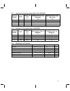
RBIAS 99 I Input for bias current-setting resistor. To achieve correct bias voltage, a 100-kΩ, 1%
tolerance resistor connected between RBIAS and AV
SS
is recommended.
REFCAP 100 I Reference decoupling capacitor. For proper decoupling, It is recommended that a
3.3 µF capacitor in parallel with a 470-pF capacitor be connected between REFCAP and
ground.
RSINL 59 I Reset input low. An active low applied to RSINL resets the TCM4300.
RSSI 2 I Received signal strength indicator. RSSI samples received signal strength.
RSOUTH 60 O Reset out high. An active high is output from RSOUTH for 10 ms after the TCM4300 is
powered up.
RSOUTL 61 O Reset out low. An active low is output from RSOUTL for 10 ms after the TCM4300 is
powered up.
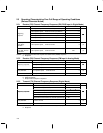
RXIN 8 I Negative receive input. The in-phase differential negative baseband received signal is
applied to RXIN.
RXIP 9 I Positive receive input. The in-phase differential positive baseband received signal is
applied to RXIP.
RXQN 5 I Negative receive input. The quadrature negative baseband received signal is applied
to RXQN.
RXQP 6 I Positive receive input. The quadrature differential positive baseband received signal is
applied to RXQP.
Intel is a trademark of Intel Corporation.
Mitsubishi is a trademark of Mitsubishi Inc.
Motorola is a trademark of Motorola, Inc.