2–3
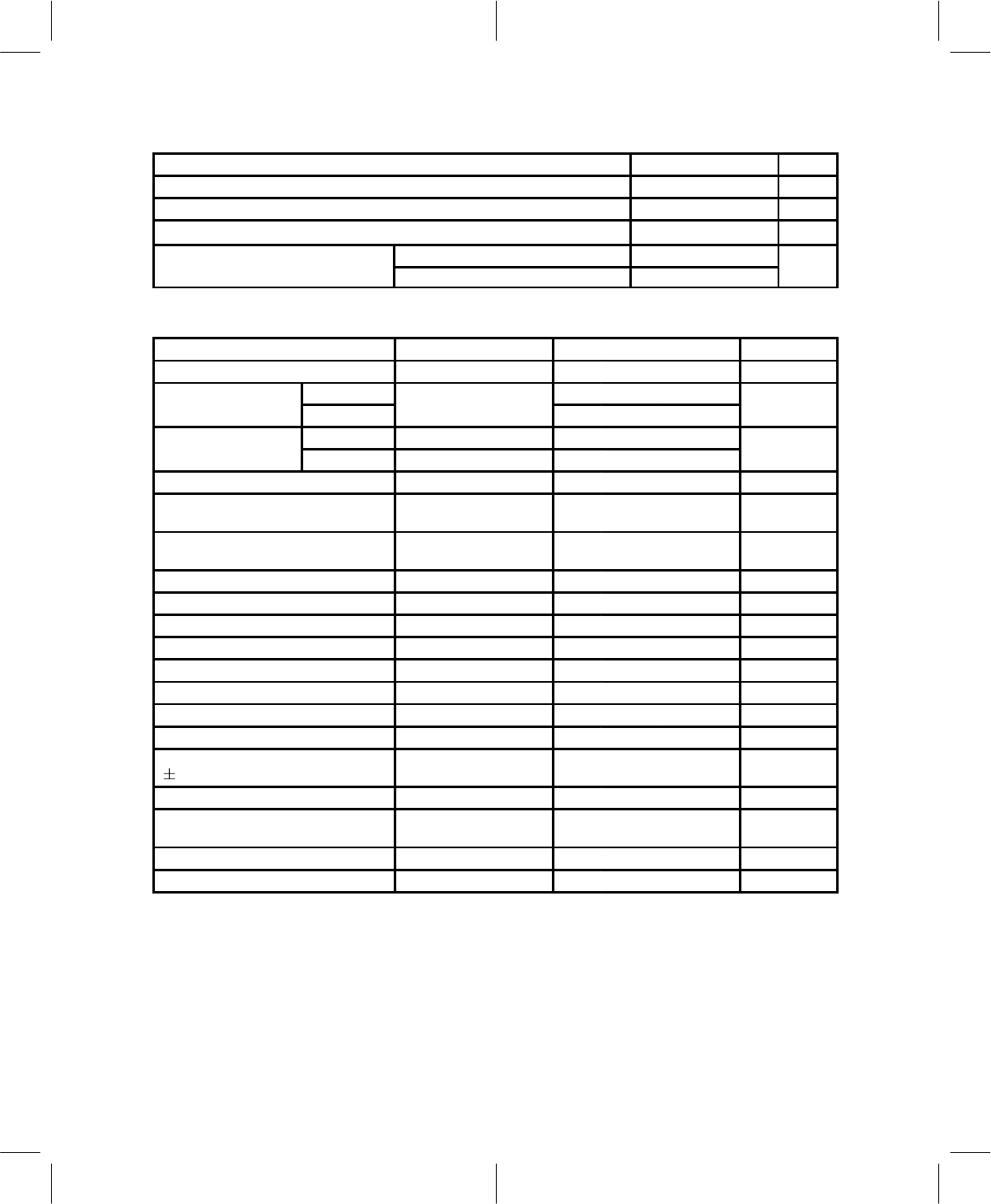
2.4.3 Terminal Impedance
FUNCTION MIN TYP
†
MAX UNIT
Receive channel input impedance (single ended), RXIP/N and RXQP/N 40 70 kΩ
Transmit channel output impedance (single ended), TXIP/N and TXQP/N 40 50 100 Ω
FM input impedance, WBD 25 200 kΩ
MCLKOUT at 3.3 V 240
mpe
ance
MCLKOUT at 5 V 180
†
All typical values are at DV
DD
= 5 V, AV
DD
= 5 V, and T
A
= 25°C, unless otherwise specified.
2.4.4 RXIP, RXIN, RXQP, and RXQN Inputs (AV
DD
= 3 V, 4.5 V, 5 V)
PARAMETER TEST CONDITIONS MIN TYP MAX UNIT
Input voltage range 0.3 AV
DD
–0.3 V
Input voltage for full-
Differential 0.5
scale digital output
Single ended
0.5
p-p
Nominal operating
Differential 0.125
level
Single ended 0.125
Vp-p
Input CMRR (RXI, RXQ) 45 dB
Sampling frequency, SINT (digital
mode)
48.6 kHz
Sampling frequency, SINT (analog
mode)
40 kHz
Receive error vector magnitude (EVM) 5% 6%
I/Q sample timing skew Input signal 0 – 15 kHz 50 ns
A/D resolution 10 bits
Signal to noise-plus distortion Input at full scale – 1 dB 54 58 dB
Integral nonlinearity 0 dB to –60 dB input 1 LSB
Gain error (I or Q channel) ±7%
Gain mismatch between I and Q ±0.3 dB
Differential dc offset voltage ±30 mV
FM input sensitivity, full scale
( 14 kHz deviation)
2.5 Vp-p
FM input dc offset (relative to VHR) ±80 mV
FM input idle channel noise, below
full-scale input
–50 dB
FM gain error ±6%
Power supply rejection f = 0 kHz to 15 kHz 40 dB
‡
Provides 12 dB headroom for AGC fading conditions.


