


3–10
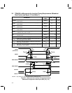
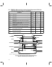
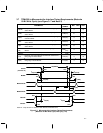
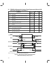
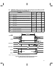
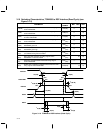
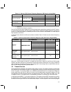
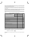
3.10 Switching Characteristics, TCM4300 to DSP Interface (Read Cycle) (see
Figure 3–10)
PARAMETER
ALTERNATE
SYMBOL
MIN MAX
UNIT
t
su(R/W)
Setup time, read/write DSPRW stable before falling edge of
strobe DSPSTRBL
TRW
(SU)
0 ns
t
h(R/W)
Hold time, read/write DSPRW stable after rising edge of
strobe DSPSTRBL
TRW
(HO)
0 ns
t
su(CS)
Setup time, chip select stable DSPCSL before falling edge
of strobe DSPSTRBL
TCS
(SU)
0 ns
t
h(CS)
Hold time, chip select DSPCSL stable after rising edge of
strobe DSPSTRBL
TCS
(HO)
0 ns
t
su(RA)
Setup time, read address DSPA stable before strobe
DSPSTRBL goes low
TWA
(SU)
0 ns
t
h(RA)
Hold time, read address DSPA stable after strobe
DSPSTRBL goes high
TWA
(HO)
0 ns
t
en(R)
Enable time, read data on falling edge of strobe DSPSTRBL
to TCM4300 driving data bus DSPD
TRD
(EN)
0 ns
t
d(DV)
Delay read data valid time on falling edge of strobe
DSPSTRBL to valid data DSPD
TRD
(DV)
50 ns
t
h(R)
Hold time, read data DSPD invalid after rising edge of
strobe DSPSTRBL
TRD
(INV)
5 ns
t
dis(R)
Disable time, read data. TCM4300 releases data bus after
rising edge of strobe DSPSTRBL
TRD
(DIS)
12 ns
90%
10%
t
h(R)
DSPA
DSPSTRBL
DSPD
t
su(R/W)
10%
DSPCSL
DSPRW
t
su(CS)
t
h(CS)
t
h(RA)
t
su(RA)
10%
10%
90%
90% 90%
t
en(R)
t
d(DV)
t
dis(R)
t
h(R/W)
Figure 3–10. TCM4300 to DSP Interface (Read Cycle)