


Mechanical Installation MultiVOIP User Guide
98
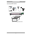
4. Turn on power to the MultiVOIP by setting the power switch on the right
side panel to the ON position. Wait for the Boot LED on the MultiVOIP to
go off before proceeding. This may take a couple of minutes.
Proceed to Chapter 4 “Software Installation.”
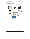
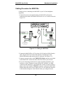
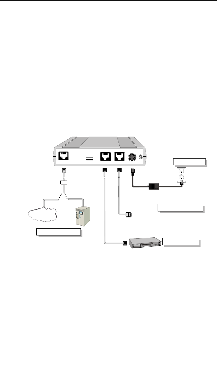
Cabling Procedure for MVP2400
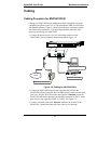
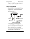
Cabling your MultiVOIP entails making the proper connections for power,
command port, phone system (T1 line connected to PBX or telco office), and
Ethernet network. Figure 3-10 shows the back panel connectors and the
associated cable connections. The following procedure details the steps
necessary for cabling your MultiVOIP.
1. Connect the power supply to a live AC outlet, then connect it to the
MultiVOIP as shown in Figure 3-10.
Power Connection
Command Port Connection
1
0
DIGITAL VOICE
TRUNK
ETHERNET
10/100
RS232
COMMAND
POWER
T1
PBX
PSTN
Telephony Connection
Network Connection
Hub
Figure 3-10: Cabling for MVP2400
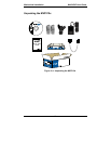
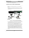
2. Connect the MultiVOIP to the PC (the computer that will hold the
MultiVOIP software) using the RJ-45 to DB9 (female) cable provided with
your unit. Plug the RJ-45 end of the cable into the Command port of the
MultiVOIP and connect the other end (the DB9 connector) to the PC serial
port you are using (typically COM1 or COM2). See Figure 3-10.
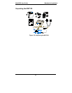
3. Connect a network cable to the Ethernet connector on the back of the
MultiVOIP. Connect the other end of the cable to your network.
4. Turn on power to the MultiVOIP by setting the power switch on the right
side panel to the ON position. Wait for the Boot LED on the MultiVOIP to
go off before proceeding. This may take a couple of minutes.