


MultiVOIP User Guide 8-Channel Analog Expansion Card
547
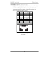
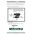
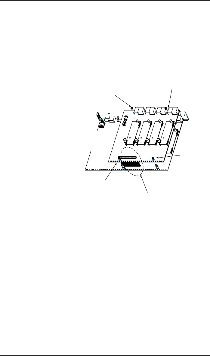
11. Locate the male 60-pin vertical connector near the LED edge of the main
circuit card. Check that pins are straight and evenly spaced. If not, then
correct for straightness and spacing. Locate the 60-pin female connector
on the upgrade circuit card.
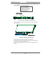
12. Set the upgrade circuit card on top of the main circuit card. Align the
upgrade card’s 4 pairs of phone-jacks with the 4 pairs of holes in the
backplane of the main card. Slide the phone jacks into the holes.
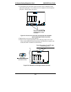
13. Mate the upgrade card’s 60-pin female connector with the main card’s 60-
pin male connector.
*
*
*
*
60-pin connectors
*
These screws (4 places)
attach upgrade card
to main card.
Figure D-7. Attaching upgrade card to main circuit card
(secure 4 Phillips screws; mate 60-pin connectors)
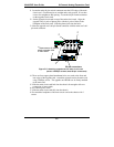
14. There are four copper-plated attachment holes, two each at the front and
rear edges of the upgrade card. Attach the upgrade card to the main card
using 4 Phillips screws. The upgrade card should now be firmly attached
to the main card.
15. Slide the main circuit card back into the chassis far enough to allow re-
connection of power cable.
16. Re-connect power cable.
17. Slide the main circuit card fully into the chassis.
18. Re-attach the backplane of the main circuit card to the chassis with 3
screws.