8-Channel Analog Expansion Card MultiVOIP User Guide
546
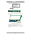
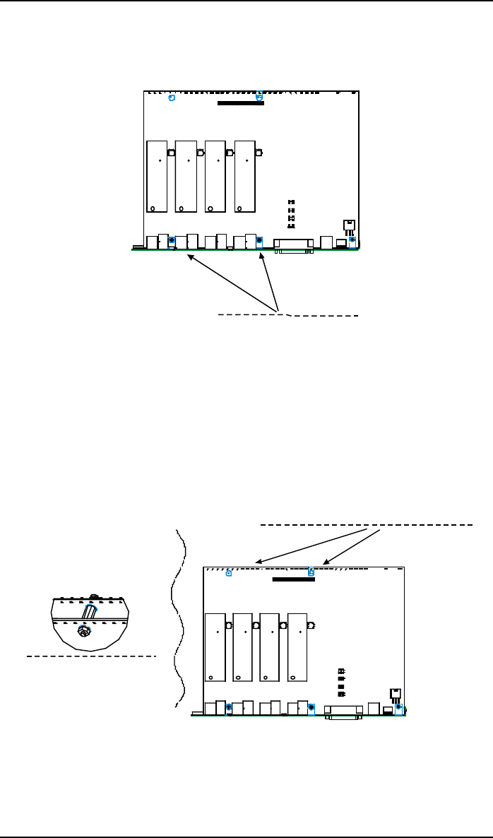
8. On the phone-jack side of the circuit card, three screws attach the circuit
card to the back panel. Two of these screws are adjacent to the four phone-
jack pairs. Remove these two screws.
Screw locations (2)
at phone-jack edge
of board.
Figure D-5: Screws to be removed and replaced with standoffs
(phone-jack edge of board; top view)
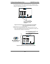
9. Replace these two screws with standoffs.
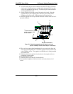
10. There are two copper-plated holes at the LED edge of the circuit card.
Place a nut beneath each hole (lockwasher side should be in contact with
board) and attach a standoff to each location).
Standoff locations (2) at LED edge
of board (top view).
Standoff/nut attachment
(rear bottom view)
Figure D-6: Standoffs at LED edge of board (top view)


