


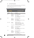

number assigned to that TalkSwitch unit). By default,
all TalkSwitch units are shipped with a unit ID of 1. This
means the extensions are 111 to 118. A TalkSwitch with
unit ID 2 would have extensions 121 to 128. For details
on setting up 2 or more units on a LAN to operate as
‘networked’ units, please see section 2.5.
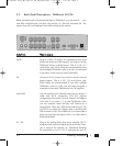
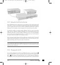
L1/L2, L2, L3/L4, L4 This is where you plug in your RJ-11 telephone lines. If
you have 2 lines out of 1 phone jack, you can plug into
the 1/2 and 3/4 jacks. Use a surge protector if you live
in an area prone to lightning strikes.
USB Use the USB port if your PC supports USB connectivity. If
you use the USB port, you can’t use the serial port simul-
taneously.
**UUSSBB ttoo bbee ssuuppppoorrtteedd iinn nneexxtt rreelleeaassee..
SERIAL Attach a serial cable (RS232) to connect TalkSwitch to
your PC.
MEMORY SLOT Located on side of box: used to expand internal memory
for Voicemail and Auto Attendant messages. TalkSwitch
Memory cards can be purchased from your local
TalkSwitch reseller or from www.talkswitch.com. Simply
place the memory card in the slot and TalkSwitch will
automatically detect and start using the extra memory
within 20 seconds.
POWER Plug the supplied AC Power Adapter in here. Rating:
16VAC 1.5 A output. Do not use any other power adapter,
as this may cause damage.
By default, TalkSwitch is set to Serial connection. To activate USB connection, dial
91 from an extension then reset TalkSwitch by turning it off and then on again.
To return to Serial connection, dial 90 and reset TalkSwitch. No commands are
required to use the LAN connection.
The ‘PF’ box in between E4 and L1/L2 represents power failure support. In the event
of a power failure or loss of power to TalkSwitch, Extension 114 will be able to receive
calls and make calls on Line 1.
4 TalkSwitch User Manual
TS manual 11th ED_CVA_v11_CD_Release.qxd 7/13/2004 3:33 PM Page 4