


28
2.2.4 Battery Voltage Monitoring Process
This terminal uses a main battery (lithium-ion battery pack) for driving the main unit, and a primary
sub-battery (lithium battery) and a secondary sub-battery (lithium-vanadium battery) for backup.
Application programs can acquire the status of these batteries through the APM BIOS or system
library. Refer to Appendix C Acquisition of Suspend/Resume Event and Power Status.
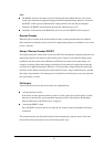
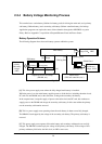
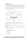
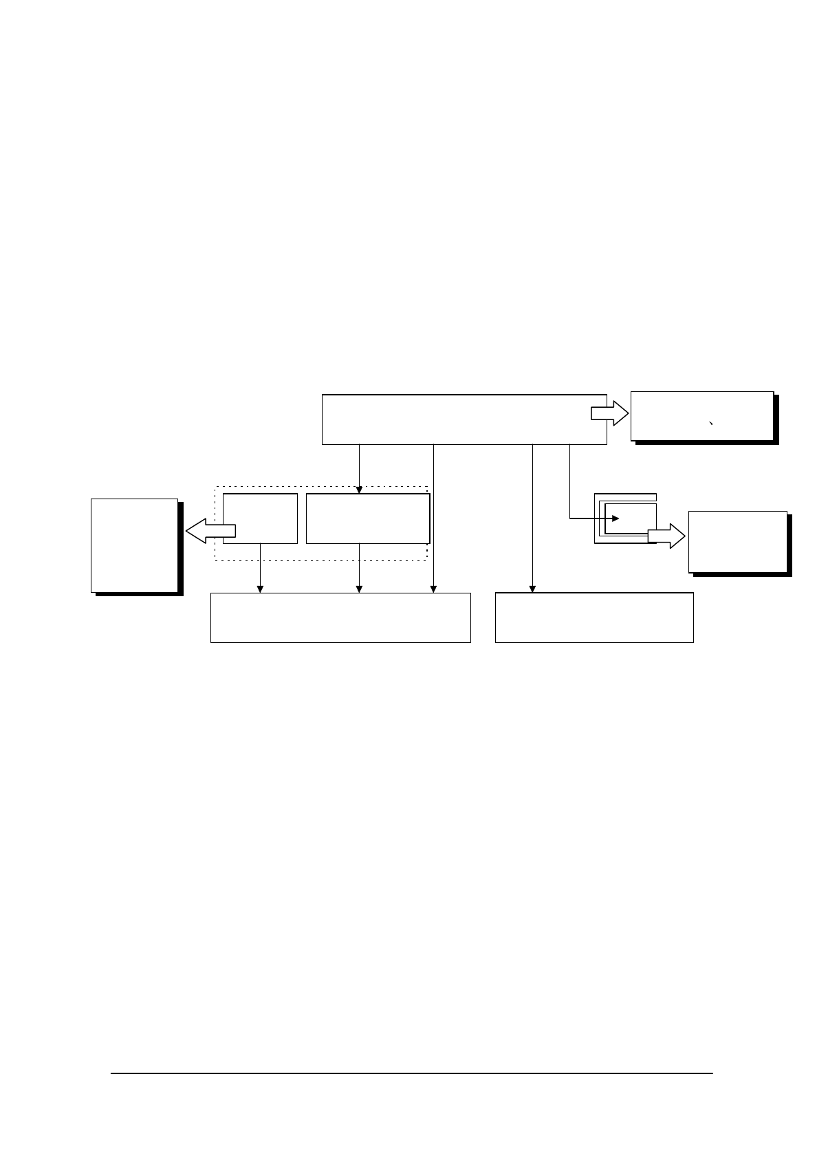
Battery Operation Scheme
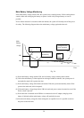
The following diagram shows how each battery operates within the system.
Fig. 2.5
[A] This is the power supply route where the fully charged main battery is installed.
While the power is on, the main battery supplies power to all the devices, including the main circuit,
PC card slot and DRAM, and, at the same time, it charges the secondary sub-battery.
In the suspend state, it stops the supply of power to the main circuit and PC card, but continues to
supply power to the DRAM and charge the secondary sub-battery. In this route neither the primary
nor the secondary sub-batteries are used.
[B] This is a power supply route operating where the main battery is absent or not fully charged.
The DRAM is back-upped by the voltage of the secondary sub-battery. The primary sub-battery is
not used.
[C] This power supply route operates if the main battery and secondary sub-batteries are not fully
charged. The DRAM is backed-up by the voltage of the primary sub-battery. If the voltage of this
primary sub-battery falls below the limit level, an LB2 event occurs.
Monitors
primary
sub-battery
voltage.
(LB2)
Main battery
Primary
sub-battery
Secondary sub-battery
(Rechargeable)
Objective devices of backup
(DRAM, etc.)
Main circuit
(CPU and controllers, etc.)
[A] Charge
[A](During ON)
SRAM Card
Sub-battery
PC Card Slot
[C]
[B]
[A]
[A]
(During ON)
Monitors main battery
voltage (LB1 LB0)
Monitors
SRAM card
voltage. (LB3)