


Mid-market to large enterprise
Issue 6 January 2008 93
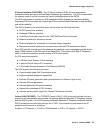
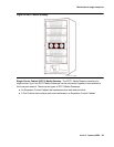
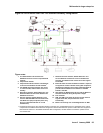
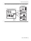
Figure 28: S8700-series fiber-PNC in a standard reliability configuration
Figure notes:
1. The Administration PC accesses the
S8700-series Server over the corporate data
network.
2. Corporate IP network.
3. Corporate IP network interface. The Ethernet
4 link from the S8700 to the data network.
1
4. Two S8700s are always present. One server
is in active mode, and the other server is on
standby.
5. Duplication interface, default Ethernet 2. The
dedicated Ethernet connection between the
S8700-series Servers.
6. Services interface, default Ethernet 1. The
server's dedicated Ethernet connection from
the S8700 to a laptop computer (active only
during on-site administration or on-site
maintenance).
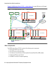
1. The Ethernet connection to the corporate network in this figure is a nondedicated network. IP addresses for the various
components of the S8700-series fiber-PNC configuration must be administered to prevent conflicts with other equipment
that shares the network. In the default S8700 fiber-PNC configuration, all other Ethernet connections operate on their
own closed LANs.
7. Network control A interface, default Ethernet 0. The
server's Ethernet connection to one or two Ethernet
switches. This Ethernet link carries the control signals
for the PNs.
8. Ethernet switch. At least one Ethernet switch is required
to support the control network. If many PNs are present,
two Ethernet switches can be daisy-chained together to
provide sufficient Ethernet connections to the IPSI
boards in the PNs.
9. UPS. Keeps the S8700-series Servers and the Ethernet
switches functional during brief power outages.
10. Port networks.
11. IPSI. The IPSI circuit pack carries the control network
signals to the PNs, and provides tone clock
functionality.
12. Bearer connectivity over Center Stage Switch or ATM.