


Network design
296 Avaya Application Solutions IP Telephony Deployment Guide
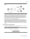
Multipath routing
Many routing protocols, such as OSPF, install multiple routes for a particular destination into a
routing table. Many routers attempt to load-balance across the two paths. There are two
methods for load balancing across multiple paths. The first method is per-packet load
balancing, where each packet is serviced round-robin fashion across the two links. The second
method is per-flow load balancing, where all packets in an identified “flow” (source and
destination addresses and ports) take the same path. IP Telephony does not operate well over
per-packet load-balanced paths. This type of setup often leads to “choppy” quality voice. Avaya
recommends that in situations with multiple active paths, per-flow load balancing is preferable to
per-packet load balancing. This behavior is enabled by default on Avaya products. On Cisco
routers, the command for this is “ip route-cache,” applied per interface.
Frame Relay
The nature of Frame Relay poses somewhat of a challenge for IP Telephony, as described in
this section.
Overview of frame relay
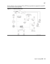
Frame Relay service is composed of three elements: the physical access circuit, the Frame,
Relay port, and the virtual circuit. The physical access circuit is usually a T1 or fractional T1 and
is provided by the local exchange carrier (LEC) between the customer premise and the nearest
central office (CO). The Frame Relay port is the physical access into the Frame Relay network,
a port on the Frame Relay switch itself.
The access circuit rate and the Frame Relay port rate must match. The virtual circuit is a logical
connection between Frame Relay ports that can be provided by the LEC for intra-lata Frame
Relay, or by the inter-exchange carrier (IXC) for inter-lata Frame Relay. The most common
virtual circuit is a permanent virtual circuit (PVC), which is associated with a committed
information rate (CIR). The PVC is identified at each end by a separate data-link connection
identifier (DLCI) in Figure 79
.