


Network design
310 Avaya Application Solutions IP Telephony Deployment Guide
Layer 2
Layer 2 configuration of the switches supporting the cluster should use IEEE 802.1w Rapid
Spanning Tree Protocol (RSTP) to prevent loops and for selection between redundant links.
Most modern switches implement this protocol. Selecting a device for Layer 2 access that does
not support RSTP should be very carefully considered since those devices are likely to be
obsolete and lacking in other highly desirable features in areas such as Quality of Service,
security, and manageability. RSTP is also preferred over most alternative solutions that are
typically not standards based and can cause problems with interoperability, scalability and
configuration complexity. Whichever redundancy protocol is selected must be well understood
by the IT staff responsible for maintaining the network.
It is good policy to enable RSTP on all ports of the Layer 2 switches, even those ports directly
connected to hosts. Remember that misconfiguration and human error are more likely to occur
than link failure and the added protection of loop avoidance is worth the minimal overhead. This
is an additional argument in favor of RSTP as the redundancy protocol to use since other
solutions may not be applicable uniformly to the subnet.
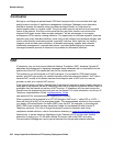
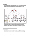
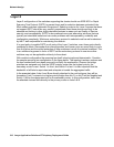
With modular configuration the spanning tree itself is kept simple and deterministic. Consider
the sample spanning tree configuration in the figure below. The topology has been redrawn and
the host connections have been removed to simplify the explanation. Assume the bridge
priorities are assigned such that the VRRP primary router has the highest priority, the
secondary router is next, Switch 1 is third, and Switch 2 is last. It is also important that the
bandwidth of all links be equivalent and adequate to handle the aggregated traffic.
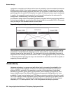
In the example below, links A and B are directly attached to the root bridge so they will be
forwarding. Link C connects to a higher priority bridge than link D, so link D will be disabled and
Switch 1 will be the designated root for the secondary router. In this configuration, traffic from
the attached devices flows directly to the primary router on links A & B.