


Traffic engineering
192 Avaya Application Solutions IP Telephony Deployment Guide
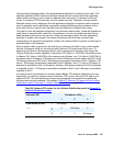
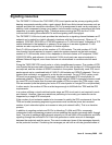
Consider the COI matrix for a three-site, stand-alone Communication Manager system, as
presented in Table 25
. A suitable expansion of that matrix might take the form of the matrix in
Table 29:
Expanded COI matrix for a three-site system on page 192 in which
● I represents IP endpoints
● C represents circuit-switched endpoints
● P represents PSTN trunks
This finer categorization of endpoints permits the use of a single COI matrix for intercom,
inbound, and outbound call usage rates.
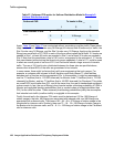
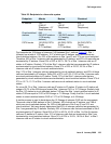
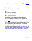
Example 4: Expanded COI matrices
In this example, we revisit Example 2: Uniform Distribution model, which pertains to the Uniform
Distribution model, in more detail. The various endpoints are grouped into the three categories
that are referenced in Table 29
. The COI matrix in Table 28 lists the intercom call usage rates
between each pair of sites, including intrasite call usage. Those usage rates can be broken
down into finer components. Table 30:
Endpoints in a three-site system on page 193 reviews
the various endpoints in each site.
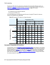
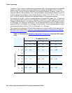
Table 29: Expanded COI matrix for a three-site system
To endpoints in Site ___
1 2 3
I C P I C P I C P
From endpoints in Site ___
1
I
C
P
2
I
C
P
3
I
C
P