


Call usage rates
Issue 6 January 2008 197
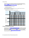
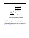
In general, one may choose to expand a COI matrix in any of several different possible ways,
depending upon the needs of the problem. In the preceding example, separating the endpoints
into IP, circuit-switched, and PSTN makes sense for the upcoming resource-sizing calculations,
as will be seen later in this document. In other examples, other sets of categories may be more
appropriate. Also, the number of categories per site is not limited to three.
COIs for multiple-site networks
The discussion of COIs up to this point has been limited to stand-alone Communication
Manager systems. It is also possible to network several Communication Manager systems
together. IP tie trunks serve as the most common mode of interconnectivity. However,
circuit-switched tie trunks are also supported.
To engineer a network of multiple Communication Manager systems, one must to know the
topology of sites within each of the individual systems, and the overall topology of the entire
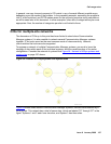
configuration. Consider the network of systems that Figure 64:
Network of Avaya systems and
system sites on page 197 shows.
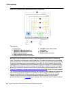
Figure 64: Network of Avaya systems and system sites
Figure 64 shows three distinct Communication Manager systems, that are interconnected by IP
trunk groups. This network has a total of seven sites, which are labeled “S1” through “S7” in the
figure. Systems 1 and 2 each have two sites, and System 3 has three sites.