


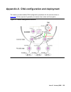

CNA configuration and deployment
364 Avaya Application Solutions IP Telephony Deployment Guide
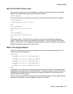
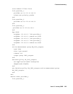
route-assert-filter force
decision-policy DP_signaling_targets
set-application-model enterprise
damped-mode disable
end
decision-policy DP_bearer_targets
set-application-model voice
damped-mode disable
end
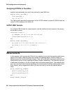
set-decision-policy DM_signaling_targets active-measurement-group
AM_signaling_targets
set-decision-policy DM_bearer_targets active-measurement-group
AM_bearer_targets
end
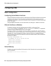
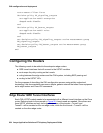
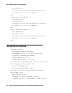
Configuring the Routers
The following needs to be added to the enterprise edge routers:
● GRE tunnel interfaces that will connect to the USTAT modules
● route maps for policy routing on the tunnels
● outing between the edge routers and the CNA system, including iBGP peering and
● routing to the USTAT VIPs
For the purposes of describing the CNA configuration process using widely understood
terminology, this documentation assumes a simple, generic network that uses Cisco equipment
as its edge routers and Cisco IOS commands.
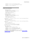
Edge Router GRE Tunnel Interfaces
Each CNA USTAT module needs to be associated with a different tunnel interface on the Cisco
router. Referring back to the example in Figure 95
, three tunnels are needed. Since there are
three USTAT modules and only two edge routers, two of the tunnels—Tunnel1 and
Tunnel2—will be created on the one edge router, while the third tunnel—Tunnel3—will be
created on the other edge router.