


Small to mid-size enterprise
Issue 6 January 2008 39
These processing elements are controlled by Communication Manager, thus offering the
complete set of Communication Manager call features to both IP users and traditional telephony
users.
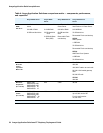
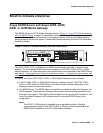
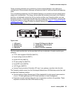
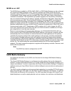
From a hardware perspective, the G700 Media Gateway is an enclosure with an internal power
supply and a motherboard. This design that provides the hardware resources for the Gateway
functions, and electrical connectivity for four media modules, one Cascade module, and one
Expansion module. The enclosure houses the power supply and the motherboard, and provides
the physical support to allow the insertion of the various modules. Figure 7:
Avaya G700 Media
Gateway (front view) on page 39 shows the Media Gateway enclosure.
Figure 7: Avaya G700 Media Gateway (front view)
The four media module slots can be populated with any combination of media module types,
including:
● T1/E1 with integrated CSU/DSU (MM710)
● 8-port analog line/trunk (MM711)
● 8-port DCP line (MM712)
● 24-port analog line (MM716)
● 8-port BRI trunk (MM720)
● VoIP Engine (MM760)
● Internal Communications Controller (ICC-only 1 per gateway; must be in the first slot)
The Cascade module comes from the Converged Infrastructure LAN Switches product line, and
provides the Octaplane interface:
● One full-duplex 4-Gbps Ethernet port (8 Gbps bandwidth) for high-speed interconnection
of up to 10 media gateways and P330 data switches in a stack arrangement
● Expansion module interface allows the use of expansion modules in the gateway. These
expansion modules also allow WAN access routing.
Figure notes:
1. LED board
2. S8300 Server
3. Services port
4. USB ports
5. Avaya P330 Expansion Module
6. 10/100 Base T Ethernet ports
7. Media Modules
8. Serial (“Console”) connector
cynds111 KLC 121003
ALM
TST
ACT
123456 87
ALM
TST
ACT
123456 87
REMOVE
ALM
TST
ACT
OK TO
SHUT DOWN
SERVICES USB 1 USB 2
E1/T1 EIA 530A DCE
ALM
TST
ACT
SIG
EISO EMSM EOSI
2
5
6
1
3
4
7
7
7
8