


909A/B universal coupler
555-233-116
28 Issue 4 October 2002
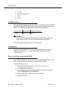
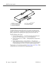
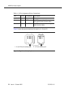
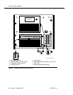
Figure 2 shows the physical locations of the pins for J1, J2, and J3.
Figure 2. Typical modular jack pinout
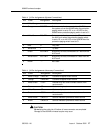
Table 4. J3 Pin Assignments (Power Connections)
Pin Color Designation Description
1, 3, 4, & 7 —— Not used
2 Black GRD -48 RET or ground lead from system or
from positive lead of power supply
5 Yellow -48 VDC -48 VDC from system or from negative
lead of power supply
1. J1 and J2 8-pin modular jacks 2. J3 7-pin modular jack
18
2
5
mod_jack RBP 041796