


DEFINITY INADS
Issue 4 October 2002
183555-233-116
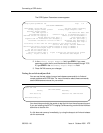
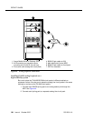
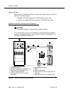
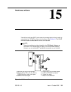
Figure 42. INADS connection (European platform)
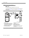
Standard reliability
■
Normal connection: Connect the INADS tip and ring port from the AUX
connector (wire pair 50 and 25) to the tip/ring pair of CO line port 1 on the
PARTNER system.
■ US/Atlas/Spain platform connection: Connect station 10 to the INADS
port.
■ European platform connection: Bridge the outside pair of CO line port 1
to the INADS port. A 258A adapter may be used.
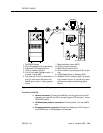
1. PARTNER System
2. MLS12D telephone for programming
3. Standard RJ-45 telephone cord
4. 103A or modular wall jack
5. Pins 2,3 on cable 5 bridge to pins 1,4
of cable 7 inside MDF
6. Dial tone from the CO or extension on
pins 2,3; with return dial tone to the
INADS port on pins 1,4 during power
failure
7. Main distribution frame (MDF)
8. PSTN or switch extension
9. B25A 25-pair cable to AUX
10. AUX connector (use wire pair 50,25, tip and
ring)
11. Avaya Media Server or Gateway PPN
12. Standard RJ-45 connector (pins 2,3, tip and
ring, connect to pins 1,4, tip and ring, when
the internal contacts close during power
failure)
1
L
I
N
E
S
E
X
T
E
N
S
I
O
N
S
PFT
PFT
206
MODU LE
R2.0
cydf206a RPY 02199
8
9
4
5
2
7
3
6
12
10
11
1234
8