


Set clock options
Issue 4 October 2002
167555-233-116
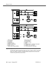
Stratum 3 clock wiring installation procedure
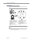
1. Connect the B25A cables from the TN780 connector panel slot on the
system cabinet and the Stratum 3 Clock to the cross-connect module in the
yellow field.
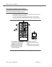
2. Connect the CSU plug end of the H-600-274 Y-cable to the primary CSU.
Route an H600-307 cable from the DS1 connector panel slot on the system
cabinet to the connector on the “SYSTEM” end of the Y-cable.
3. Route a B25A cable from the “CLOCK” end of the Y-cable to the cross-
connect module in the yellow field.
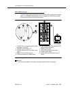
4. Repeat steps 2 and 3 for the secondary CSU. The maximum allowable
cabling distance between the Stratum 3 clock and the CSU is shown in the
table below.
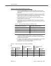
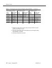
5. For standard reliability systems, refer to Y-cable to cross-connect the
TN780 and “CLOCK” end connections to the Stratum 3 clock connections
on the cross-connect module.
6. For high or critical reliability systems, refer to table below to cross-connect
the TN780 and “CLOCK” end connections to the Stratum 3 clock
connections on the cross-connect module.
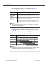
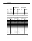
Table 19. Maximum cabling distance for different CSUs
Channel Service Unit (CSU) Maximum Cabling Distance
551A 85 feet (27 m)
551V 85 feet (27 m)
551V EFS/R 755 feet (199.7 m)
EFS T1 755 feet (199.7 m)
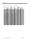
Table 20. Y-cable clock-end cross-connects for reliability
From Stratum 3 Clock
To Y-cable clock end
(primary)
To Y-cable clock end
(secondary)
Lead
Name
Lead Color/
Te rmi na l
Lead
Name
Lead Color/
Te rm ina l
Lead
Name
Lead Color/
Te rmi na l
RREF1 W-BL/1 V-O/43
TREF1 BL-W/2 O-V/44
RREF2 W-O/3 V-O/43
TREF2 O-W/4 O-V/44