


For MCC1, SCC1, CMC1, and G600 Media Gateways
Issue 4 October 2002
193555-233-116
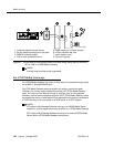
3. Connect a cable from the assigned port carrier slot to J1 on the 909A/B
universal coupler (see Chapter 1, ‘‘909A/B universal coupler’’). A wiring
block must be locally engineered.
a. Connect the T-lead at pin 5 and the R-lead at pin 4 of J1 on the
909A/B universal coupler to the corresponding leads from the
TN2183.
b. Connect the CT-lead at pin 5 and the CR-lead at pin 4 of J2 on the
909A/B universal coupler to the MDF.
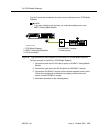
4. Install patch cord/jumper wires at the MDF to connect tip and ring to the
information outlet at the music source.
5. Set the Protection/Paging switch to C1.
6. Connect a modular cord from the information outlet to the music source.
7. Connect -48V to pin 5 and -48V RET to pin 2 of J3 on the 909A/B. The
power source may be an 1151A, 1151A2, or other approved power supply.
8. Administer the switch for the new equipment.
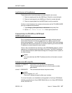
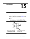
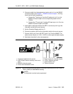
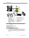
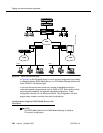
Figure 46. Typical nonregistered equipment connections (auxiliary access) for an MCC1,
SCC1, CMC1, or G600 Media Gateway
NOTE:
A wiring block must be locally engineered.
1. Customer-supplied music source
2. A25D 25-pair cable to auxiliary trunk circuit
pack
3. 909A/B universal coupler
4. Part of main distribution frame
5. Power supply for universal coupler
6. 103A or modular wall jack
7. 4-pair modular cord
8. Tip and ring wires
J2
J3
J1
5
2
4
5
4
5