


Malicious call trace
555-233-116
190 Issue 4 October 2002
NOTE:
A wiring block must be locally engineered.
NOTE:
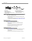
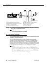
909A couplers ships with one DW4B-DE cable and two DW8B-SE cables.
The 909B ships with one KS-22911L2 power supply, one DW4B-DE cable,
and two DW8B-SE cables.
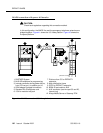
1. Determine the port assignment of the recorder from the malicious call
tracing form.
2. Install the 909A/B universal coupler on a vertical surface.
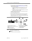
3. Connect the SZ, SZ1, S, and S1 leads from the 909A/B to an auxiliary trunk
circuit pack.
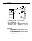
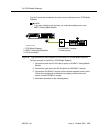
a. Tip and ring connect from the voice recorder to the auxiliary trunk
circuit pack (J1 on the 909A/B).
b. CBS1/C1 and CBS2/C2 connect from the voice recorder to J2 on
the 909A/B.
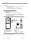
4. On the 909A/B universal coupler:
a. Connect seizure control voltage of from -9 to -70 Volts to the PG2/
BZ2 connection (pin 2 of J1). Switching voltage to the PG2/BZ2
connection can be from the 909A/B -48 VDC supply.
b. Connect SZ1 to the ground lead of the DC power source used for
PG2/BZ2.
c. Set S1 to the “C2” position. Set S2 position 7 to “OPEN”.
d. Connect an approved -48 VDC power source to the -48 and GRD
terminals (pins 5 and 2, respectively, of J3 on the 909A/B).
5. Administer the switch for the call trace device.