


Wideband endpoints
Issue 4 October 2002
209555-233-116
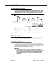
Main distribution frame connection
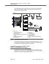
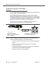
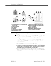
Figure 57 illustrates the main distribution frame method which connects a Avaya
Media Server DS1 interface circuit pack, with a 25-pair cable to the MDF, to the
customer-supplied digital line PC board in the MMCX, through a D8W cable.
Figure 57. MMCX connected to an Avaya Media Server through the MDF
Wideband endpoints
Wideband endpoints include video equipment or bridges/routers for LANs. Use
the running list that accompanies the system to make cable connections.
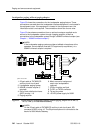
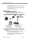
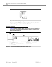
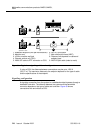
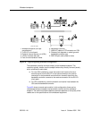
Nonsignaling configuration
A nonsignaling connection to a wideband endpoint may connect to a channel
service unit (CSU). If not using a CSU, the distance between the system and the
endpoint is limited to a few hundred feet. See Figure 58. The maximum distance
depends on the type of cable and type of endpoint.
NOTE:
The MM710 media module (for the G700 Media Server) has a built-in
channel service unit (CSU). Therefore, the CSU in Figure 58 and Figure 59,
plus the references in the accompanying text about distance limitations
when working without a CSU, do not apply to a G700 Media Gateway
configuration.
1. Avaya Media Server
2. DS1 interface circuit pack
3. 25-pair cable
4. Main distribution frame (MDF)
5. Public telephone network
6. 103A or modular wall jack
7. D8W 4-pair modular cord
8. MMCX server