


Paging and announcement equipment
555-233-116
204 Issue 4 October 2002
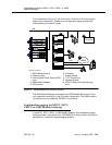
7. Connect a 2-pair line cord (modular plug at one end) from the information
outlet to the loudspeaker system.
8. Install loudspeaker equipment according to the manufacturer’s instructions.
9. Connect an approved -48 VDC power source to the -48 and GRD terminals
(pins 5 and 2, respectively, of J3).
10. Administer the switch for the new equipment.
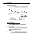
ESPA radio paging
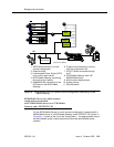
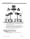
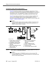
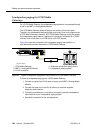
Figure 53 shows typical connections to European Standard Paging Access
(ESPA) equipment. Connect the LINE jack on the PassageWay interface to a
digital line 4-wire DCP circuit pack through the MDF.
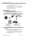
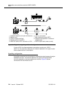
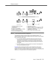
Figure 53. Typical ESPA radio paging connections
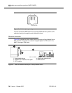
NOTE:
The G700 Media Gateway does not support an auxiliary trunk media
module. Therefore, the loudspeaker paging feature through an auxiliary
trunk is not supported on a G700 Media Gateway.
ECC G700 Media Gateway users can access this equipment if equipment is
physically connected to a TN763 auxiliary trunk circuit pack in an EPN
carrier of an ECC system.
1. DCP telephone
2. 4-pair modular cord
3. PassageWay interface
4. 4-pair modular cord
5. 103A or modular wall jack
6. To digital line circuit pack
7. RS-232 connector
8. ESPA radio paging equipment
9. Loudspeaker paging system
cydf004 RPY 12309
7
PHONE
LINE
POWER
1
2
3
4
5
6
7
8
9