


Wideband endpoints
Issue 4 October 2002
211555-233-116
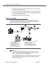
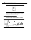
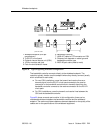
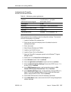
Figure 59. Typical signaling wideband configuration
The bandwidth controller connects directly to the wideband endpoint. The
controller typically installs near the endpoint where they directly connect (usually
within a few feet of each other).
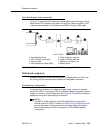
■ For non-CSU installations, cross the transmit and receive lines so a
transmit signal from the DS1/E1 circuit pack connects to the receive
connection on the bandwidth controller and a transmit signal from the
bandwidth controller connects to the receive connection on the DS1/E1
circuit pack.
■ For CSU installations, cross the transmit and receive lines between the
CSU and the bandwidth controller.
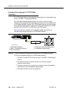
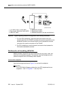
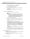
Figure 60 shows a remote port module. In this configuration, there can be
considerable distance between the bandwidth controller and the wideband
endpoint. The maximum distance between elements depends on the quality of the
cables and on the specifications of the wideband equipment.
1. Wideband endpoint (wire per
manufacturer)
2. To DS1/E1 circuit pack
3. Optional channel service unit (CSU)
4. 103A or modular wall jack
5. Part of main distribution frame
6. Bandwidth controller
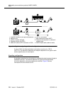
7. H600-307 cable to DTE connector on CSU
8. Distance limit depends on cable type and
bandwidth controller type
9. A25D 25-pair cable (male-to-male)
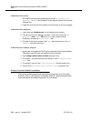
AUX PORTCOM PORT MODEM
DTE
NETWORK
POWER
c
y
df047 PDH091396