


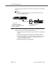


Loudspeaker paging for MCC1, SCC1, CMC1, or G600
Media Gateways
Issue 4 October 2002
203555-233-116
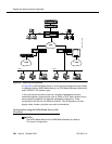
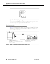
Loudspeaker paging access without universal
coupler
1. Determine port assignment of paging zone(s) from loudspeaker paging
form.
2. At the main distribution frame, locate the connecting block and terminals
assigned to the selected port.
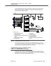
3. On the locally engineered wiring block, place a strap between terminals S
and SZ. Place a strap between terminals S1 and SZ1.
4. Install patch cord/jumper wires at the main distribution frame.
5. Connect a 2-pair line cord (modular plug at one end) from the information
outlet to the paging amplifier (to the loudspeaker system).
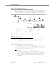
6. Install loudspeaker equipment according to the manufacturer’s instructions.
7. Administer the switch for the new equipment.
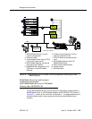
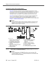
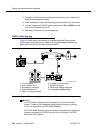
Loudspeaker paging with universal coupler
An information outlet provides access to loudspeaker paging. The system side of
the main distribution frame connects to a 909A/B universal coupler. Make
provisions for the DC power that the 909A/B universal coupler requires, such as a
1151A, 1151A2, or other approved -48VDC power supply.
Six leads (T, R, SZ, SZ1, S, and S1) connect the adapter to an auxiliary trunk
circuit pack located in a port carrier.
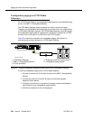
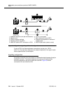
1. Determine port assignment of paging zone(s) from loudspeaker Paging
form.
2. Identify carrier slot and label both ends of an A25D (male to male) cable.
3. Connect a cable from the 909A/B to the system side of the main
distribution frame. A wiring block must be locally engineered.
4. Chapter 1, ‘‘909A/B universal coupler’’ provides details of the connections
between the 909A/B universal coupler and the wiring blocks.
!
CAUTION:
Damage to the 909A/B may occur if the cable is plugged into J3
before all cross-connects are completed.
5. On the 909A/B universal coupler:
■ Connect seizure control voltage of from -9 to -70 volts to the PG2/
BZ2 connection (pin 2 of J1). Switching voltage to the PG2/BZ2
connection can be from the 909’s -48-volt supply.
■ Connect a -48 VDC power source to the -48 and GRD terminals on
the 909A/B.
6. Install patch cord/jumper wires at the main distribution frame.