


Loopback testing with a smart jack
Issue 4 October 2002
143555-233-116
Releasing the DS1 circuit pack
NOTE:
If you have a G700 Media Gateway, substitute XXXVS for UUCSS in the
following command, where XXX is the administered number of the G700 (for
example, 002), and VS is the slot number on the G700 of the Media Module
(for example, V3). The V is not a variable and needs to be included in the
command exactly where shown. A sample address for a DS1 circuit pack on
a G700 Media Gateway might look like this: 002V3.
1. Release the DS1 circuit pack. From the management terminal, enter
release board UUCSS, where UU is the cabinet number, C is the carrier
letter, and SS is the slot number of the DS1 board.
2. Leave the loopback jack in place.
Testing the DS1 span from the smart jack to the
network interface termination or fiber
multiplexer (MUX)
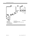
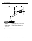
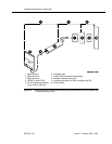
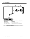
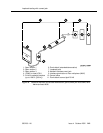
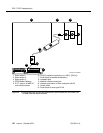
1. Have the service provider run a smart-jack loopback test against the
network interface wiring that links the smart jack to the CO (section 3 in
Figure 24 through Figure 29).
2. If the tests fails, there is a problem on the network side. Have the service
provider correct it.
Testing the DS1 span from the loopback jack to
the smart jack
Test the short length of customer premises wiring between the loopback jack and
the smart jack (Section 2 in the following 3 figures) using a loopback that overlaps
this section of the span.
■ Have the DS1 service provider at the CO end run a local ICSU line
loopback test.
■ Have the DS1 service provider at the CO end run a local DS1 payload
loopback test.
■ Run a far-end ICSU line loopback, using the procedure below.
NOTE:
This test cannot isolate the problem if there are problems in the wiring
between the far-end CO and the far-end ICSU. You must coordinate
this test with the DS1 service provider.