


Paging and announcement equipment
555-233-116
202 Issue 4 October 2002
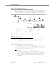
Loudspeaker paging without paging adapter
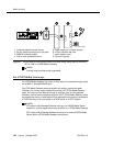
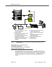
Figure 52 shows the connections for the loudspeaker paging feature. These
connections are used when the loudspeaker interface equipment is not located in
the equipment room. If the equipment is located in the equipment room, the
information outlet is not required. The connections shown are for one zone.
Figure 52 also shows connections from an optional customer-supplied music
source to the loudspeaker system through a paging amplifier, as well as
connections to the loudspeaker system through a 909A/B universal coupler (see
Chapter 1, ‘‘909A/B universal coupler’’).
NOTE:
If the loudspeaker paging system provides a talkback microphone at the
speakers, the microphone must be FCC approved (or equivalent), or a
909A/B universal coupler is required.
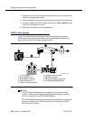
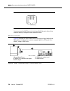
Figure 52. Connections for loudspeaker paging without paging adapter for an MCC1,
SCC1, CMC1, or G600 Media Gateway
NOTE:
On the 25-pair cable to TN763B/C/D auxiliary trunk circuit pack, SZ1
connects to GRD on key 10. The 50 points amphenol is connected to the
back of a G600 Media Gateway.
1. 25-pair cable to TN763B/C/D
auxiliary trunk circuit pack
2. Loudspeaker paging system
3. 909A/B universal coupler (if
required)
4. Part of main distribution frame
(MDF) circuits 1-16
5. Paging amplifier
6. Music source for background
music over loudspeakers
(optional)
7. 103A or modular wall jack
8. To SZ1 on TN763 connector
9. Tip and ring wires
10. -48 VDC power supply for 909B
cydfnzm KLC 091202
J2
J3
J1
5
1
2
2
7
4
4
5
2
3
6
5
1
2
3
4
5
7
8
9
9
10
6