


Installation Procedure
Preconfigure the IPC-1600 Boards
Set the starting controller memory address (DS1, SW8—1), the I/O
address (DS1, SW11—9), and the IRQ level (DS2, SW8—1) for each IPC-1600
to be installed. Note that IRQ levels are not used by the MS-DOS driver.
Therefore all DS2 switches should be set to the OFF position (Note 2). Refer
to Appendix A, “Hardware Parameter Settings,” for switch location and
decode information.
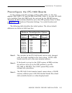
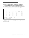
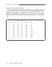
The following table identifies the initial options. The driver default
addresses are shown in bold type face.
Note 1:
Note 2:
Note 3:
Hardware Preconfiguration Options
Memory
Address
80000h
90000h
A0000h
B0000h
C0000h
D0000h
E0000h
Input/Output
Address
100h
110h
120h
200h
220h
300h
320h
Interrupt
Request
Set all
switches
to OFF
(Note 2)
The switches on the IPC-1600 board can be easily changed
with the board installed in the host system. All IPC-1600
boards must be set to the same memory address.
If the board is set up for the UNIX system, all IRQ switches
do not have to be set to the OFF position to use the
IPC-1600 in MS-DOS. The UNIX system IRQ switch
settings take precedence.
The IPC-1600 (16-bit transfer board) cannot share a 128-KB
memory address space with 8-bit transfer boards like a hard
disk controller board or a video display board.
MS-DOS DEVICE DRIVER INSTALLATION 2-3