


Installation Information
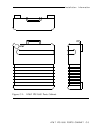
Installing the 16-Ports Fanout Module
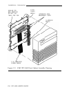
It is recommended that the upper position of the two mounting positions
be used first to facilitate easy addition of the second 16-Ports Fanout module.
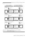
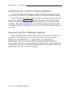
The 16-Ports Fanout module snaps into the wire-frame assembly from the
front of the assembly (Figure C-2). First put the slot on the left side of the
16-Ports Fanout module over the wire tab on the left side of the wire-frame
assembly. Then slide the right side of the 16-Ports Fanout module into the
wire-frame assembly until the two slots on the right of the module engage the
wire tabs.
Connecting Port Modular Cables
When connecting the modular cables to the 16-Ports Fanout module, it is
important to label (identify) the circuit(s). The label information should
include the port identification (ttyxyy) and the connecting device
identification. After the modular cables are properly labeled (identified),
connect each cable to the corresponding port and route the cable through the
wiring guides. Be sure to connect the ground lead of the modular cable to the
ground lug on the 16-Ports Fanout module.
C-4 IPC-1600 USER’S GUIDE