


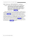


Installation Information
Choosing a Mounting Location
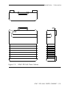
The AT&T IPC-1600 Ports Cabinet must be located within about 7 cable
feet (2 meters), the length of the fanout module cable assembly, of the host
machine.
The method of mounting (floor, table, or wall) is a matter of convenience
for your particular installation. The most physically secure method of
mounting the cabinet is to fasten it to a stable surface. Secure-type mounting
is recommended to protect the connections and apparatus.
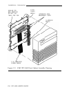
Securing the Wire-Frame Assembly
The wire-frame assembly can be placed, unsecured, on the floor or table.
However, it is recommended that the assembly be fastened to a stable surface
to provide a physically secure installation.
When securing the wire-frame assembly to a stable surface, make sure of
the proper placement of the assembly in relation to the host system.
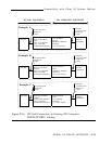
Routing and Connecting Ribbon Cables to the
Fanout Module
The ribbon cables are routed behind the wire-frame assembly with the
“lead 1” identifiers on the left as viewed in Figure C-2. It is recommended
that the upper position of the two mounting positions be used first to facilitate
easy addition of the second 16-Ports Fanout module.
The connectors on the 16-Ports Fanout module and the ribbon cables are
keyed for proper alignment. When connecting the ribbon cables to the
16-Ports Fanout module, be sure that the retaining clips are properly secured.
First, connect the ribbon cable nearest the front of the wire-frame
assembly to the 16-Ports Fanout module connector for ports 9 through 16.
Then connect the other ribbon cable for ports 1 through 8.
AT&T IPC-1600 PORTS CABINET C-3