


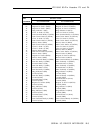
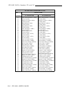
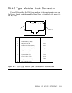
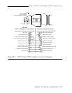
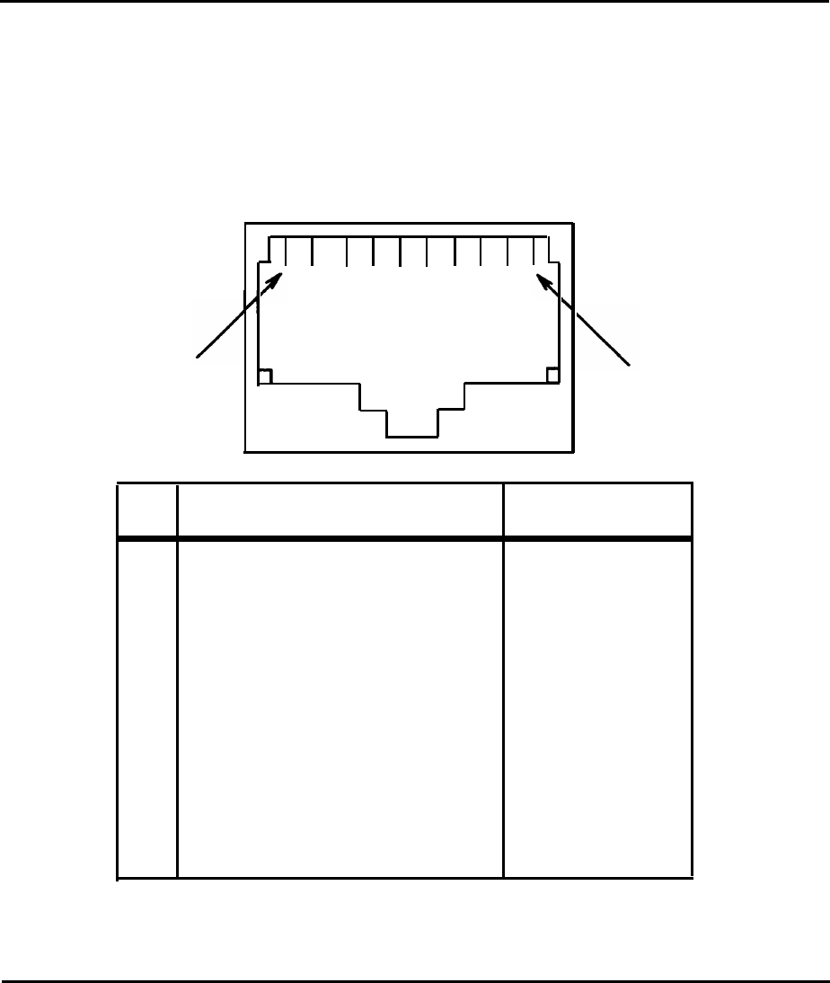
RJ-45 Type Modular Jack Connector
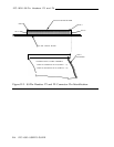
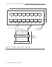
Figure B-4 identifies the RJ-45 type modular jack connector pins used on
the 16-port fanout module assembly. Signal flow is identified with respect to
the IPC-1600.
2
PIN 1
3 4 5 6 7 8 9
PIN 10
PIN
SIGNAL NAME
SIGNAL FLOW
1
Data Set Ready (DSR)
Input
2
Ring Indicator (RI)
Input
3
Data Carrier Detect (DCD)
Input
4
Data Terminal Ready (DTR)
Output
5
Signal Ground (SG)
Bidirectional
6
Receive Data (RD)
Input
7
Transmit Data (TD)
Output
8
Clear To Send (CTS)
Input
9
Request To Send (RTS)
Output
10
No Connection (NC)
-
Figure B-4: RJ-45 Type Modular Jack Connector Pin Identification
SERIAL I/O DEVICE INTERFACE B-9