


Commander Installation Guide
Issue 9 Trilogy Communications Limited Page 9 of 81
2. INSTALLATION
2.1 INTRODUCTION
Follow the sequence below, step by step, to install the Commander matrix.
• Unpack the matrix
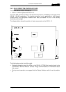
• Fit the matrix frame and power supplies into the equipment bay
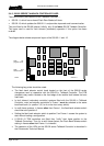
• Load the modules into the matrix frame, in sequence
• Apply power to the system and check basic operation.
• Connect control panels and check operation with the supplied flash ram configuration.
• Set up the configuration PC.
2.2 UNPACKING
Carefully unpack the equipment from its transit material and check each item for signs of
damage.
Check the contents of the boxes against our despatch note and your original order to ensure
that you have received the correct parts.
In the event that the unit has been damaged or does not match your order, immediately
contact Trilogy Communications at the address given at the front of this guide.
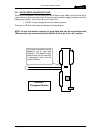
2.3 RACK MOUNTING
The Central Matrix is built in multiples of 6U. The depth (excluding mating connectors) is
420mm. Control Panels are standard 19” rack mounting units; most panels are 2U although
a series of 1U panel are available and custom panels may be 3U or larger. The Power
Supply requires additional space – see Section 2.5 for further details.
It is most likely that a s
ystem contractor or Trilogy personnel will install the central matrix.
Suitable care should be taken with cooling and ventilation within the equipment bay. There
are a number of internal connections between racks of multiple rack systems. Refer to the
Technical Guide or Trilogy Communications for further details.
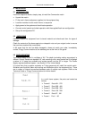
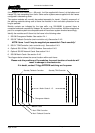
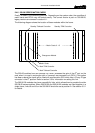
In a multi frame system, the ports are located as
follows:
¾ Frame 6 Ports 481 - 576
¾ Frame 5 Ports 385 - 480
¾ Frame 4 Ports 289 - 384
¾ Frame 3 Ports 193 - 288
¾ Frame 2 Ports 97 - 192
¾ Frame 1 Port 1 - 96