


Commander Installation Guide
Trilogy Communications Limited Page 55 of 81
Issue 9
7. OTHER EQUIPMENT
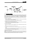
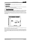
7.1 BELTPACKS
Beltpacks may be connected to the Commander matrix on ports configured as 4-wire. They
require an external voltage supply, either +15V or ± 15V depending on the type number. The
Commander PSU (500-15-30) provides a 4 pin XLR socket with ± 15V protected by an
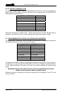
internal self resetting fuse. See section 2.5 for connector details. The tables below show the
different belt
box types available.
Type No. of input
channels
(from matrix)
Fixed Connector type Mating Connector type
required
Supply
voltage
required
Headset
connector
(socket)
410-50-02 1 XLR6 Male XLR6 Female +15V B-gauge
¼” jack
410-50-03 2 Hirose 12 Way Plug
RM15TRD-12P
Hirose 12 Way Socket
RM15TPD-12S
± 15V B-gauge
¼” jack
410-50-12 1 XLR6 Male XLR6 Female +15V XLR5
Female
410-50-13 2 Hirose 12 Way Plug
RM15TRD-12P
Hirose 12 Way Socket
RM15TPD-12S
± 15V XLR5
Female
Notes:
1. All Beltpacks have one output channel (i.e. return to the matrix).
2. The Beltpack PTT (talk) switch is normally momentary action. The -12 and -13 types
may be ordered with a latching talk switch, using part codes -12-L and -13-L.
3. The -02 and -03 variants are discontinued with effect December 2008.
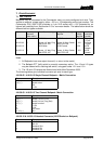
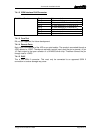
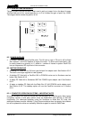
The following tables give individual connector pin-outs for each type.
410-50-02 / 410-50-12 Single Channel Beltpack – Matrix Connection
Pin Function
1,2 (+,-) Audio from box
3,4 (+,-) Audio to box
5 0V
6 +15V
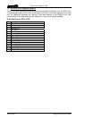
410-50-03 / 410-50-13 Two Channel Beltpack– Matrix Connection
Pin Function
1 Chassis
2,3 (+,-) Audio 1 to box (PTB)
4,5 (+,-) Audio 2 to box (Prog Snd)
6,7 (+,-) Audio from box
8 +15V
9 -15V
10 0V to box
11,12 (+,-) N/c
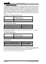
410-50-12 & 410-50-13 Headset Connector (XLR5 Socket on Beltpack)
Pin Function
1 Mic IN (Screen)
2 Mic IN
3 Headset Gnd
4 Headset Out
5 Headset Out