


Commander Installation Guide
Trilogy Communications Limited Page 45 of 81
Issue 9
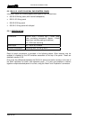
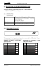
Keypad D9 Fixed Socket
Pin Function Notes
1 Column 1 Switch 1,4,7, *
2 Column 3 Switch 3,6,9,#
3 Row 2 Switch 4,5,6
4 Row 4 Switch *,0,#
5 GND For switch LEDs
6 Column 2 Switch 2,5,8,0
7 Row 1 Switch 1,2,3
8 Row 3 Switch 7,8,9
9 +12V out Switch
View of Keypad (as seen on front panel)
1 2 3
4 5 6
7 8 9
0 #
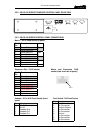
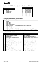
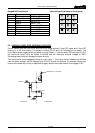
5.8 CONTROL PANEL GPIO EXTERNAL CIRCUITRY
Control panels from the 500-3x-30 and 500-3x-50 range provide 2 local GP inputs and 2 local GP
outputs on a D9 fixed socket. The tables in section 8.5.2.2 and 5.5.3 provide pin-out details. The
circuit below
gives suggested wiring details for Logic Output 1. Like the matrix GPI card (see 3.4.5.2)
the maxi
mum current must be limited to 200mA and the maximum external voltage to 200V.
Exceeding these limits will damage the panel circuitry.
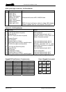
The circuit below shows suggested wiring for Logic Input 1. If the input circuitry needs to be isolated
from the panel voltage, the link between pins 5 and 9 should be removed. An external voltage can
now be connected to pin 9 but an additional dropper resistor should be added if this voltage is >5V.
EXTERNAL Vcc (200V Max)
OUTPUT 1
R
6
7
1
LINK
200mA MAX
CHASSIS
220R
Control Panel Outside World