


Commander Installation Guide
Page 12 of 81
Issue 9
Trilogy Communications Limited
2.4.2 500-02 SERIES TALKBACK CONTROLLER CARD
There are currently two versions of the Talkback Controller: -.
• 500-02-11, which has on-board Flash Ram fitted at all times
• 500-02-12, which updates the 500-02-11 and provides improved serial communication.
They are fitted to the 500-08 (above). Initially, only fit the lower 500-02 Talkback Controller.
The upper card is used for fault tolerant (redundant) operation if this option has been
ordered.
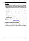
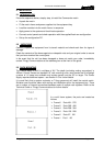
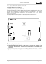
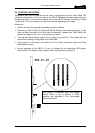
The diagram below shows component layout of the 500-02-11 and -12.
The following key points should be noted:
• The flash bank selector control knob located on the front of the 500-08 series
changeover card is inoperative with the 500-02-1x Talkback Controller. The PCB
mounted rotary switch located on the front edge of the module itself selects the boot
flash bank.
• In fault tolerant (redundant controller) systems fitted with the 500-02-1x Talkback
Controller, main and standby controllers in Frame 1 must be selected to the same
boot flash bank (i.e. position 1,2,3 or 4 on the front rotary switch).
• In multi-frame systems, in frames other than Frame 1, the flash bank selector switch
should be set to position 6.
• Setting the flash bank selector switch to position 5 on Frame 1 causes the system to
start without loading a configuration.
• If 500-01-10 TDM controllers are fitted, they "notify" their frame position to the
Talkback Controllers. Thus, for a multi-frame system, the Flash Bank Selector switch
setting in frames other than Frame 1 is irrelevant.
• The operation of the LEDs on the 500-02 series Talkback Controller is described in
the Commander Technical Manual.
500
-
02
-
11
Flash Re-
program socket
Flash boot
selector switch
Reset