


Commander Installation Guide
Issue 9 Trilogy Communications Limited Page 17 of 81
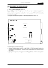
2.6 STARTING THE SYSTEM
The system may now be powered and will load a configuration from the Flash RAM. The
miniature rotary switch on the front edge of the 500-02 Talkback Controller selects the boot
configuration bank. In a multi-frame system, this is the 500-02 Talkback Controller in Frame
1 of the matrix. It is not necessary to have the computer operating at this stage.
A few hints:
• Initially, do not fit the redundant (standby) controller modules.
• Remove any 500-10 Misc I/O cards and 500-25 Network Link cards temporarily. If they
have not been included in the initial boot configuration (loaded from Flash RAM), the
system will appear not to run, or will operate very slowly.
• Turn the flash bank selector switch “out of range” (e.g. position 5). The system will now
start without loading a configuration from flash RAM.
• If the system is multi-frame, see Section 2.4.2 for further information about the Flash
RAM
selector switch.
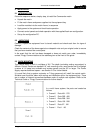
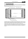
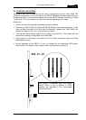
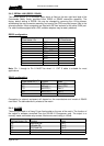
• Normal operation of the 500-01-10 card is indicated by the alternating LED pattern
shown below. The display rotary selector switch should be set to position 3.
This pattern is displayed when the Display
Select Switch is set to position 3. Other
patterns are described in the Commander
Technical Manual.