


Commander Installation Guide
Trilogy Communications Limited Page 79 of 81
Issue 9
10. CONTROL PANEL CONFIGURATION
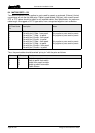
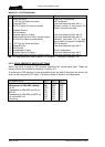
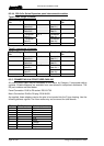
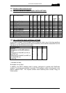
10.1 500-3X-5X SERIES INTERNAL PANEL SWITCH SETTINGS
Id DIP Switch Action DIP
1
DIP
2
DIP
3
DIP
4
DIP
5
DIP
6
DIP
7
Legacy
Emul.
DIP
8
5/8
Char
0 8 Key or Desktop OFF OFF OFF OFF OFF OFF OFF OFF
1 8 Key Expansion ON OFF OFF OFF OFF OFF OFF OFF
2 16 Key OFF ON OFF OFF OFF OFF OFF OFF
3 16 Key Expansion ON ON OFF OFF OFF OFF OFF OFF
4 24 Key OFF OFF ON OFF OFF OFF OFF OFF
5 24 Key Expansion ON OFF ON OFF OFF OFF OFF OFF
8 8 REN Expansion OFF OFF OFF ON OFF OFF OFF OFF
9 12 REN Expansion ON OFF OFF ON OFF OFF OFF OFF
10 32 Channel Level Control OFF ON OFF ON OFF OFF OFF OFF
11 12 Key 1U ON ON OFF ON OFF OFF OFF OFF
12 15 Key 1U Expansion OFF OFF ON ON OFF OFF OFF OFF
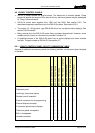
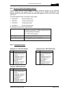
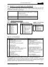
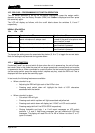
10.2 500-41 DESKTOP PANEL INTERNAL SETTINGS
A three way connector inside the panel may be fitted with links in any of the three positions
labelled H, L or M. These provide the same functionality as the switches accessible from the
top edge of the 500-30 series control panel.
Cut Switch Action H L M
No action
X X X
Changeover to HSet MIC (default)
√
X X
LS cut
X
√
X
Changeover to HSet MIC and LS cut
√ √
X
Panel MIC cut
X X
√
Changeover to HSet MIC and MIC cut
√
X
√
LS cut and MIC cut
X
√ √
Everything
√ √ √
√ indicates link fitted
X indicates link not fitted
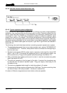
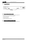
In addition, the 500-41 desktop panel is factory configured to operate with PathFinder
systems. To set the panel software to emulate T-Edit systems, solder a shorting link in the
position labelled R130. This requires surface mount soldering tools: contact Trilogy for
further advice.