


Commander Installation Guide
Page 16 of 81
Issue 9
Trilogy Communications Limited
2.5 MAINS CONNECTION AND FUSING
2.5.1 500-15-30 SERIES POWER SUPPLY
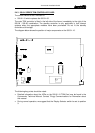
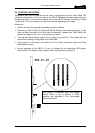
The PSU chassis occupies an additional 2U of rack space below the matrix and is internally
wired. The complete assembly therefore occupies 8U for a 96 port system, 14U for a 192
port system etc. The PSU is half rack width allowing two PSU modules to be fitted, thus
providing backup operation.
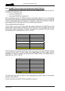
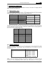
Each power supply is fitted with a D9 socket, which provides a relay contact indicating the
PSU status. The table below gives details. Connection should only be made to the pins
indicated: any other connections may cause failure of the power supply unit. There is also an
auxiliary power connector: details below.
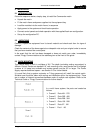
D9 Fixed Plug Pin Function
1 Relay normally closed
2 Relay normally open
3 Relay common
XLR4 Fixed Socket Pin Function
1 0V
2 +15V
3 No connection
4 -15V
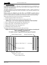
The power supplies are switched-mode units and will cope automatically with an input
voltage of between 98 and 260 volts AC. This should be wired according to the instructions
provided with your mating mains socket using suitable cable. See below for earthing details.
The mains plug has an integral fuse tray fitted with a 20mm glass cartridge slow blow/anti-
surge fuse. The fuse rating is marked adjacent to each fuse tray.
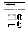
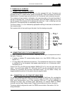
2.5.2 EARTHING REQUIREMENTS
The Trilogy 500-15-30 units are provided with a single 4mm-earthing stud on the rear panel.
Incoming mains earth from the IEC connector is internally bonded to both the chassis and
technical 0V to meet safety requirements and performance specifications. The stud allows
the addition of an earth strap in rack installations.
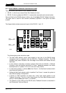
Note: The Aux power connector is protected by an internal self-resetting thermal fuse. Left
and right (main and standby) supplies may be connected in parallel.