


Commander Installation Guide
Trilogy Communications Limited Page 75 of 81
Issue 9
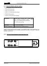
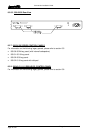
8.5.6 500-39-30 / 31 1U 12 KEY PANEL WITH LOUDSPEAKER
This panel provides more basic facilities than the 500-30 range. It does not have LCD
displays and only provides connection to the matrix, audio I/O and the test port at the rear.
An installation specification is given below.
Dimensions 485mm wide x 44.5mm high x 150mm deep
(excluding connectors) 200m approx. (including
mating connectors)
19” x 1RU rack mounting
Mains Input 90 – 260 V ac, 50-60Hz
Current Consumption 150mA @ 90V ac, 50mA @ 250V ac.
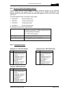
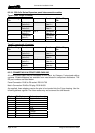
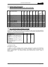
8.5.6.1 500-39-30 Connector Pin Out
Matrix – D9 Fixed Plug
Pin Function
1 NC (Screen)
2 Data Out-
3 Data In-
4 Audio Out-
5 Audio In-
6 Data Out +
7 Data In +
8 Audio Out +
9 Audio In +
Test– D9 Fixed Socket
Pin Function
1 Analyse Input
2 Enable Remote Boot
3 Ground
4 Transputer Link Out +
5 Transputer Link In +
6 Error signal Out
7 Reset In
8 Transputer Link Out-
9 Transputer Link In-
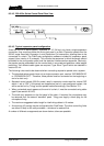
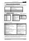
Headset - 5 Pin XLR Fixed
Socket (front panel)
Pin Function
1 Mic IN (Screen)
2 Mic IN
3 Headset Gnd
4 Headset Out
5 Headset Out
Audio I/O – D15 Fixed Socket
Pin Function Notes
1 Slave Mic Input Line level, un-balanced
2 +15V Out (for slave mic panel) NOT protected!
3 Clean Mic Out + Line level, balanced, pair with 11
4 Ext CUT Input (for slave mic panel) Parallel function to front panel Cut
Switch. Ground to activate
5 Chassis Ground
6 No connection
7 External Input to LS Amp - Line level, balanced, pair with 14
8 Matrix Audio Input to Panel / parallel output - Line level, balanced, pair with 15
9 Ext Mic Cut output (to slave panel) Normally grounded. O/P is open
circuit when front panel cut selected.
10 -15V Out (for Slave mic panel) NOT protected
11 Clean Mic Out - Line level, balanced, pair with 3
12 Mic Ground
13 Loudspeaker Output 8 ohm loudspeaker
14 External Input to LS Amp + Line level, balanced, pair with 7
15 Matrix Audio Input to Panel / parallel output + Line level, balanced, pair with 8
NB 15V supplies are also used to derive 12V for panel. (Thermally Fused @ 0.7A)
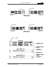
The 500-39-31 panel includes an additional expansion connector, logic GPIO signals and
footswitch connector in the same format as the 500-3x-3x series expansion panels. It is only
available to special order. See section 8.5.2.2 for connector details.