


Commander Installation Guide
Trilogy Communications Limited Page 71 of 81
Issue 9
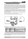
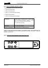
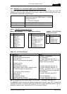
8.5.4 500-40-0X SERIES EXPANSION PANELS
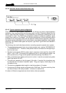
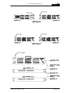
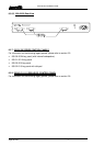
Control Panels may be linked together to provide additional facilities at one operating
position. Additional level controls (RENs) or switches may be added. Alternatively, two
standard panels from the 500-30 series may be linked together and will only utilise a single
matrix port.
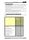
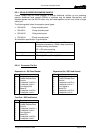
The following detail refers to expansion panel types:
• 500-40-00 8 way encoder panel
• 500-40-01 12 way encoder panel
• 500-40-02 15 key switch panel
• 500-40-04 32 way encoder panel
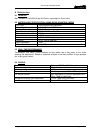
An installation specification is given below.
Dimensions 485mm wide x 44.5mm high x 100mm deep
(excluding connectors) 150mm deep (maximum
including mating connectors)
19” x 1RU rack mounting
Mains Input 90 – 260 V ac, 50-60Hz
Current Consumption 150mA @ 90V ac, 50mA @ 250V ac.
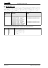
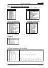
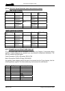
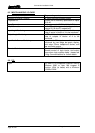
8.5.4.1 Connector Pin Out
Expansion In - D9 Fixed Socket
Pin Function
1 Analyse Input
2 Enable Remote Boot
3 Ground
4 Transputer Link Out +
5 Transputer Link In +
6 Error signal Out
7 Reset In
8 Transputer Link Out-
9 Transputer Link In-
Test Port– D9 Fixed Socket
Pin Function
1 Analyse Input
2 Enable Remote Boot
3 Ground
4 Transputer Link Out +
5 Transputer Link In +
6 Error signal in
7 Reset Out
8 Transputer Link Out-
9 Transputer Link In-
Expansion Out– D9 Fixed Socket
Pin Function
1 Analyse Input
2 Enable Remote Boot
3 Ground
4 Transputer Link Out +
5 Transputer Link In +
6 Error signal in
7 Reset Out
8 Transputer Link Out-
9 Transputer Link In-