


Commander Installation Guide
Page 14 of 81
Issue 9
Trilogy Communications Limited
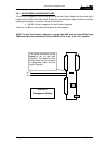
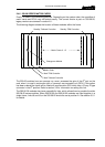
2.4.4 500-25-00 E1 NETWORK LINK CARD
This optional card has a number of front mounted LEDs and a D9 programming socket. The
system will normally be assembled by Trilogy with the appropriate rear connector units
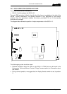
(RCU). Check the rear of the frame for the Network RCU (500-26-00) which is fitted with two
RJ45 connectors and a single BNC. Fit any Network cards in the correct places.
• Inter-system connections are described in Section 4.1..
Operation of the LEDs is described
in Section 3.4.5.3.
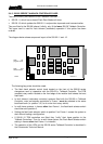
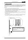
2.4.5 500-10 SERIES MISC. I/O (GPI) CARDS.
This optional board has an LED bar graph array plus a number of miniature rotary switches
on the front panel. The system frame will normally be assembled by Trilogy with appropriate
rear connector units (RCU). Check the rear of the frame for the Misc. I/O RCU, which is fitted
with 25 way and 37 way connectors, and then fit the 500-10 in the correct places.
• Input and output connector pin-outs are given in Section 3.4.5.
•
Suggested external input and output circuitry is shown in Section 3.4.5.2.
•
Operation of the front panel rotary switches and LEDs is described in Section 3.4.5.1.
•
Further information about the on-board links may be found in the Commander Technical
Manual.
• Talkback controller types 500-02-11 and 500-02-12 support a maximum of six 500-10-00
GPI cards.