


Commander Installation Guide
Page 26 of 81
Issue 9
Trilogy Communications Limited
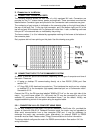
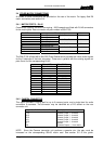
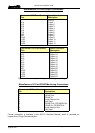
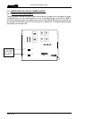
Miscellaneous I/O Card Output Connections
Commander D25 Fixed Socket
Pins
Upper Connector
Description
1 Ground
2/14 Output 1
3/15 Output 2
4/16 Output 3
5/17 Output 4
6/18 Output 5
7/19 Output 6
8/20 Output 7
9/21 Output 8
10/22 Output 9
11/23 Output 10
12/24 Output 11
13/25 Output 12
Commander D25 Fixed Socket
Pins
Lower Connector
Description
1 Ground
2/14 Output 13
3/15 Output 14
4/16 Output 15
5/17 Output 16
6/18 Output 17
7/19 Output 18
8/20 Output 19
9/21 Output 20
10/22 Output 21
11/23 Output 22
12/24 Output 23
13/25 Output 24
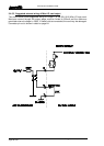
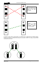
Typical external circuitry for the logic outputs is given on Page 28.
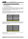
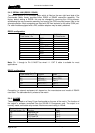
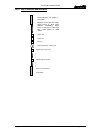
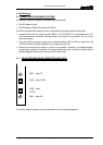
Miscellaneous I/O Card RS422/Monitoring Connections
Commander D9 Fixed Socket
Pin
Description
1 Ground
2 RS422 Out-
3 RS422 In-
4 Audio Monitor Out-
5 Not Used
6 RS422 Out+ OR RS232 Out
7 RS422 In+ OR RS232 In
8 Audio Monitor Out+
9 Not Used
Further information is available in the 500-10 Technical Manual, which is available on
request from Trilogy Communications.