


Commander Installation Guide
Trilogy Communications Limited Page 69 of 81
Issue 9
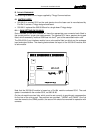
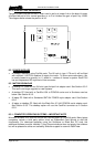
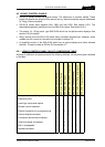
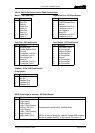
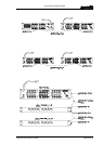
8.5.2.2 500-3x-3x Series Control Panel Connections
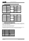
Matrix – D9 Fixed Plug
Pin Function
1 NC (Screen)
2 Data Out-
3 Data In-
4 Audio Out-
5 Audio In-
6 Data Out +
7 Data In +
8 Audio Out
9 Audio In +
Test Port– D9 Fixed Socket
Pin Function
1 Analyse Input
2 Enable Remote Boot
3 Ground
4 Transputer Link Out +
5 Transputer Link In +
6 Error signal Out
7 Reset In
8 Transputer Link Out-
9 Transputer Link In-
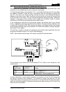
Headset - 5 Pin XLR Fixed Socket
(Front panel)
Pin Function
1 Mic IN (Screen)
2 Mic IN
3 Headset Gnd
4 Headset Out
5 Headset Out
Expansion Port– D9 Fixed Socket
Pin Function
1 Analyse Input
2 Enable Remote Boot
3 Ground
4 Transputer Link Out +
5 Transputer Link In +
6 Error signal in
7 Reset Out
8 Transputer Link Out-
9 Transputer Link In-
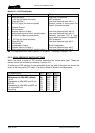
Foot Switch - D9 Fixed Socket
Pin Function
1 Foot Switch Input
2 No Connection
3 Chassis Ground
4 No Connection
5 No Connection
6 Ground
7 No Connection
8 No Connection
9 No Connection
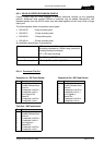
GPIO (Local logic in and out) - D9 Fixed Socket
Pin Function Notes
1 Ground
2 Logic Input 1
3 Logic Input 2
4 Logic 2 Out Common
5 Internal +5V (Out) Protected with series 44R & 1N4002 diode.
6 Logic Output 1
7 Logic 1 Out Common
8 Logic Output 2
9 Logic Input +VCC NB Pin 9 may be driven by external voltage (With dropper
resistor if greater than 5V), or by internal +5V via pin 5.